Control device

a technology of control device and articulation, which is applied in the field of control device, can solve the problem that the control device cannot always be used in an optimal manner, and achieve the effect of affecting the behavior of the two articulation areas relative to one another

Inactive Publication Date: 2012-05-10
AESCULAP AG
View PDF3 Cites 34 Cited by
  • Summary
  • Abstract
  • Description
  • Claims
  • Application Information

AI Technical Summary

Benefits of technology

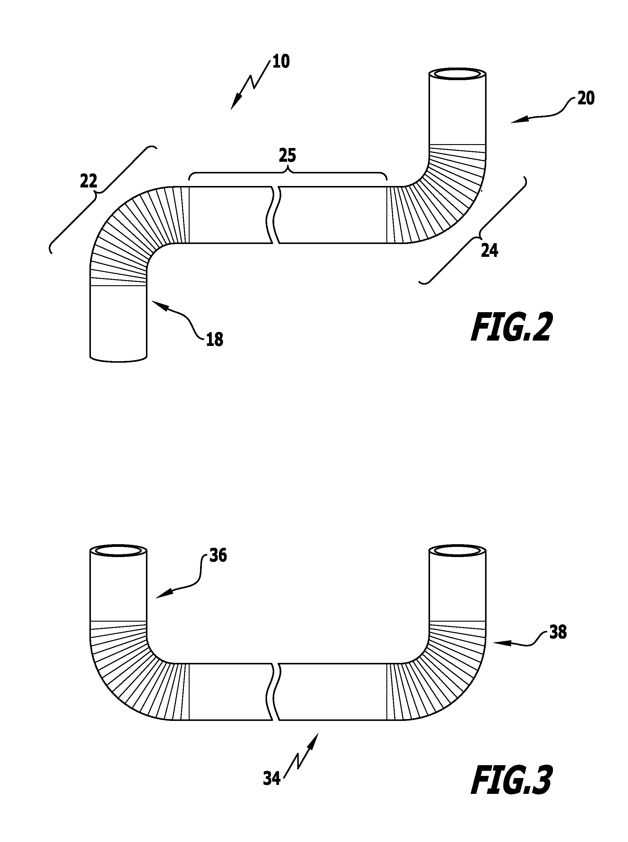
[0060]It may, in particular, be provided for the proximal and the distal areas of articulation to be of a different design, in particular also be designed with different lengths, so that a corresponding pivoting movement of the proximal area of articulation results in a smaller or intensified pivoting movement of the distal end section.
[0061]It may be provi

Problems solved by technology

With a whole series of applications both in the mechanical and in the medical field, a movement at the proximal e

Method used


Image

  • Control device
  • Control device
  • Control device

Examples


Embodiment Construction

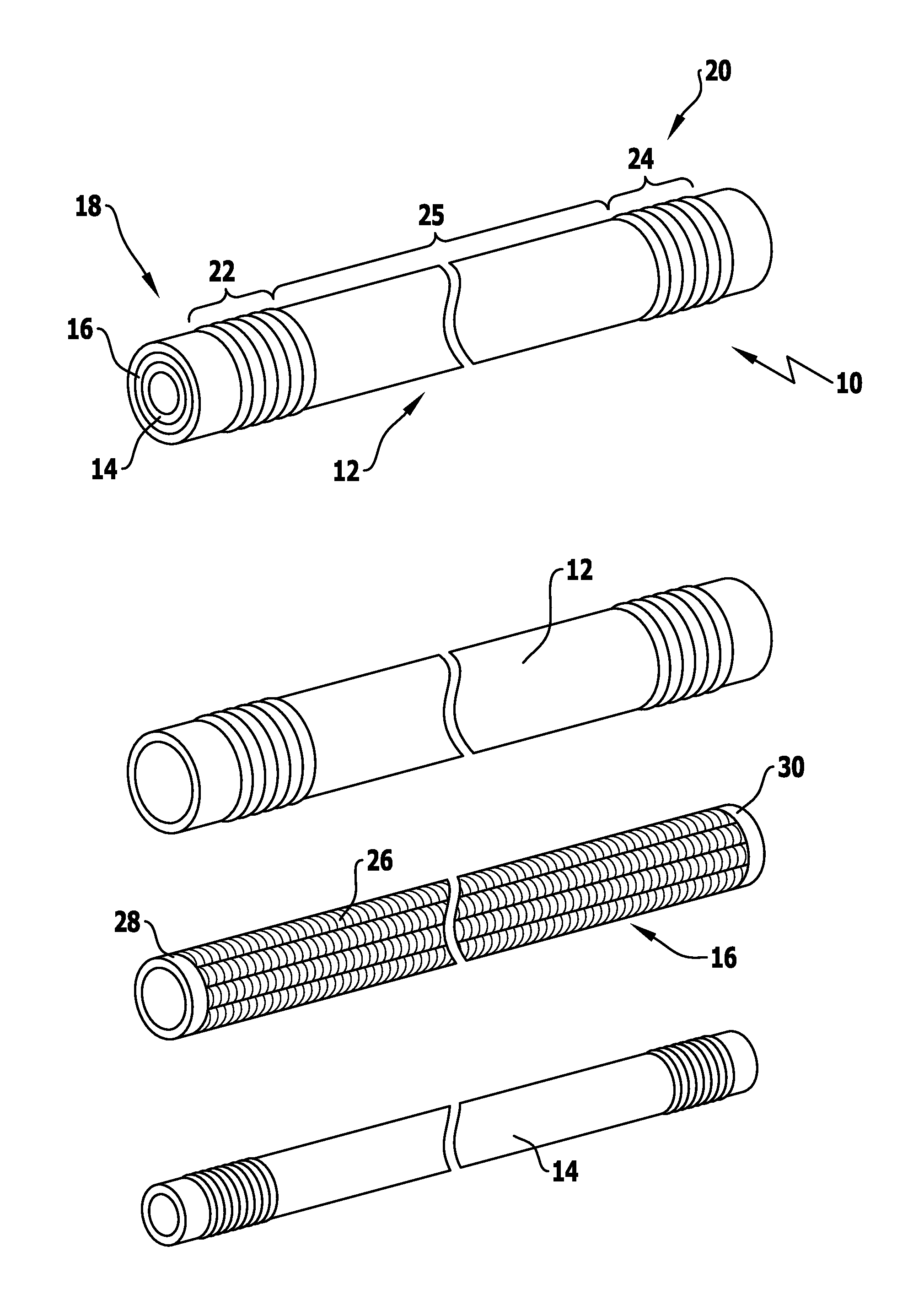
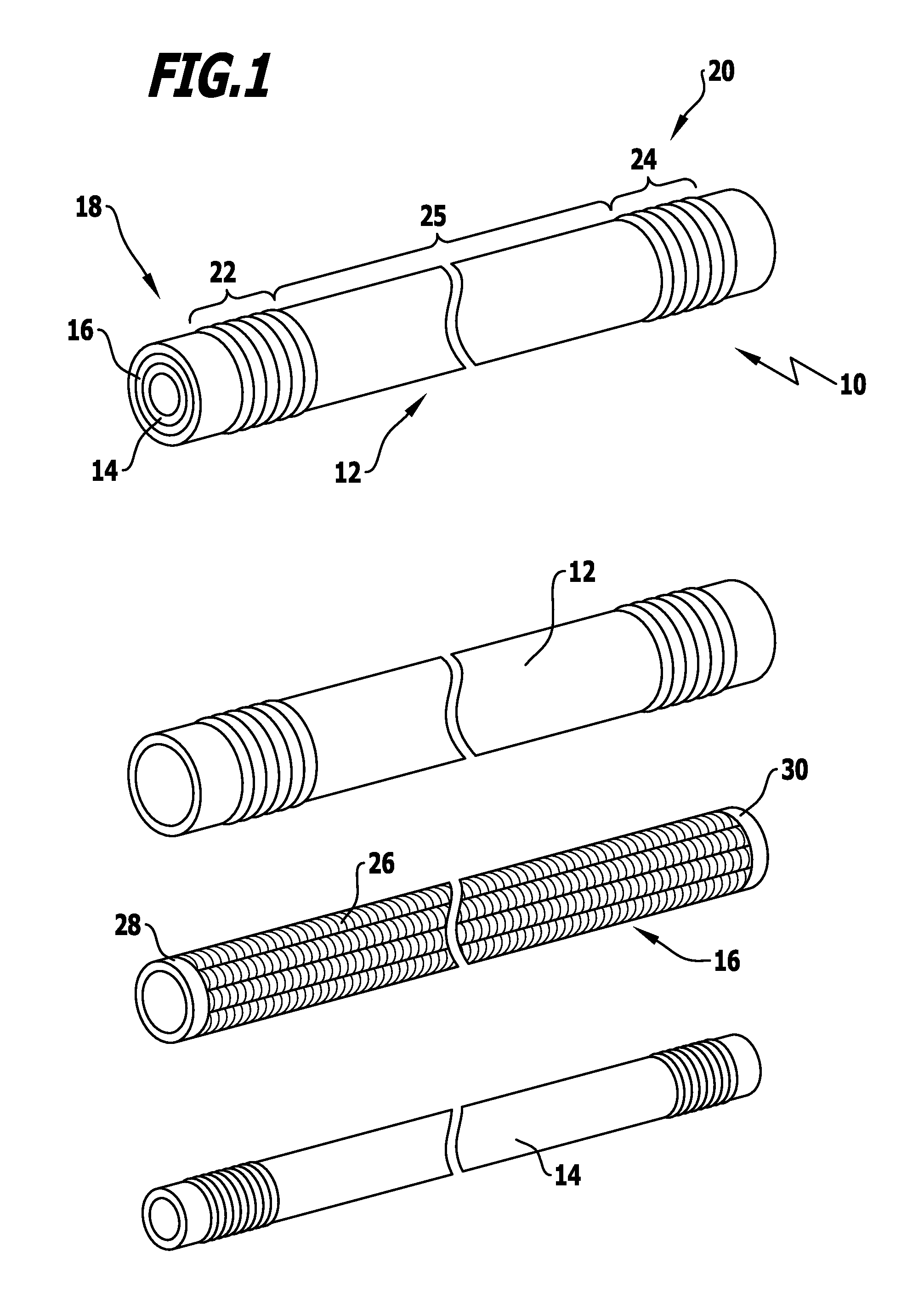
[0080]FIG. 1 shows the construction of a control device 10, as known from the state of the art, for example WO 2005 / 067785 A1.

[0081]In this respect, the control device 10 comprises an outer hollow cylindrical shaft 12, an inner hollow cylindrical shaft 14 as well as a control element 16 arranged between these shafts.

[0082]The outer and the inner shafts 12, 14 as well as the control element 16 have essentially the same length and are dimensioned with respect to their outer and inner diameters or wall thicknesses such that the control element can be pushed into the outer shaft with an exact fit and the inner shaft 14 into the interior of the control element 16 with an exact fit. The interior of the inner shaft 14 remains as lumen free for the introduction of instrument controls, feed lines to a camera or other optical elements and the like. The control element 16 is guided in a radial direction by the walls of the outer and the inner shafts 12, 14.

[0083]The control device 10 has a pro...


PUM


Abstract

A control device is provided, in particular for use in endoscopes or the like. The control device has proximal and distal end sections each comprising an area of articulation and a central section arranged therebetween. The control device also comprises outer and inner hollow cylindrical shafts and a control element arranged between the shafts. Two or more longitudinal elements extend substantially from the proximal to the distal end section and transfer force. For an optimized control function, the longitudinal elements are arranged at essentially regular angular distances in a circumferential direction of the control device and are connected to one another in the circumferential direction in the region of their respective proximal and distal ends. The distal ends of the longitudinal elements are secured in the circumferential direction in angular positions which are different to the angular positions, in which the respectively associated proximal ends are secured.

Description

[0001]This application is a continuation of international application number PCT / EP2010 / 055281 filed on Apr. 21, 2010 and claims the benefit of German application number 10 2009 024 238.4 filed on May 29, 2009 and German application number 10 2009 042 488.1 filed on Sep. 14, 2009.[0002]The present disclosure relates to the subject matter disclosed in international application number PCT / EP2010 / 055281 of Apr. 21, 2010 and German applications number 10 2009 024 238.4 of May 29, 2009 and number 10 2009 042 488.1 of Sep. 14, 2009, which are incorporated herein by reference in their entirety and for all purposes.BACKGROUND OF THE INVENTION[0003]The invention relates to a control device for precision mechanical or surgical applications, for example for use in endoscopes or the like.[0004]The invention relates, in particular, to a control device for instruments for extremely exact mechanical applications or surgical applications in the minimally invasive field.[0005]Such control devices ar...

Claims


Application Information

Patent Timeline
IPC IPC(8): A61B1/00
CPCA61B1/00071A61B1/00135A61B1/0051A61B1/0052A61B2017/2905A61B1/008A61B17/00A61B2017/003A61B2017/00309A61B1/0055
Inventor LUTZE, THEODORHEGEMANN, OLAF
Owner AESCULAP AG
Why Eureka
Try Eureka