
Laser guided auto collimation system and method for medical apparatus

Inactive Publication Date: 2012-05-10
GENERAL ELECTRIC CO
View PDF5 Cites 9 Cited by
  • Summary
  • Abstract
  • Description
  • Claims
  • Application Information

AI Technical Summary

Benefits of technology

[0028]The embodiments described herein simplify the work flow of automatic collimation for a medical apparatus, provide automatic collimation and help to improve patient experience.

Problems solved by technology

From this it can be seen that this type of system cannot realize completely automatic collimation of a patient.
Precise collimation of an irradiation landmark on the body surface of a patient by using this method takes a long time and the work flow is rather complicated.
U.S. Pat. No. 5,590,665 discloses a laser guided lesion localization apparatus, but the apparatus does not perform collimation at an irradiation landmark on the body surface of a patient.
However, the apparatus is complex in structure and inconvenient in operation.

Method used


Image

  • Laser guided auto collimation system and method for medical apparatus
  • Laser guided auto collimation system and method for medical apparatus
  • Laser guided auto collimation system and method for medical apparatus

Examples


Embodiment Construction

[0034]The present invention is described in detail by way of specific embodiments, but the present invention is not merely limited to this.

[0035]Below the specific embodiments are described in detail in conjunction with the drawings, these embodiments are not intended to limit the present invention. In the following text, the same reference number is used for the same component part in different figures.

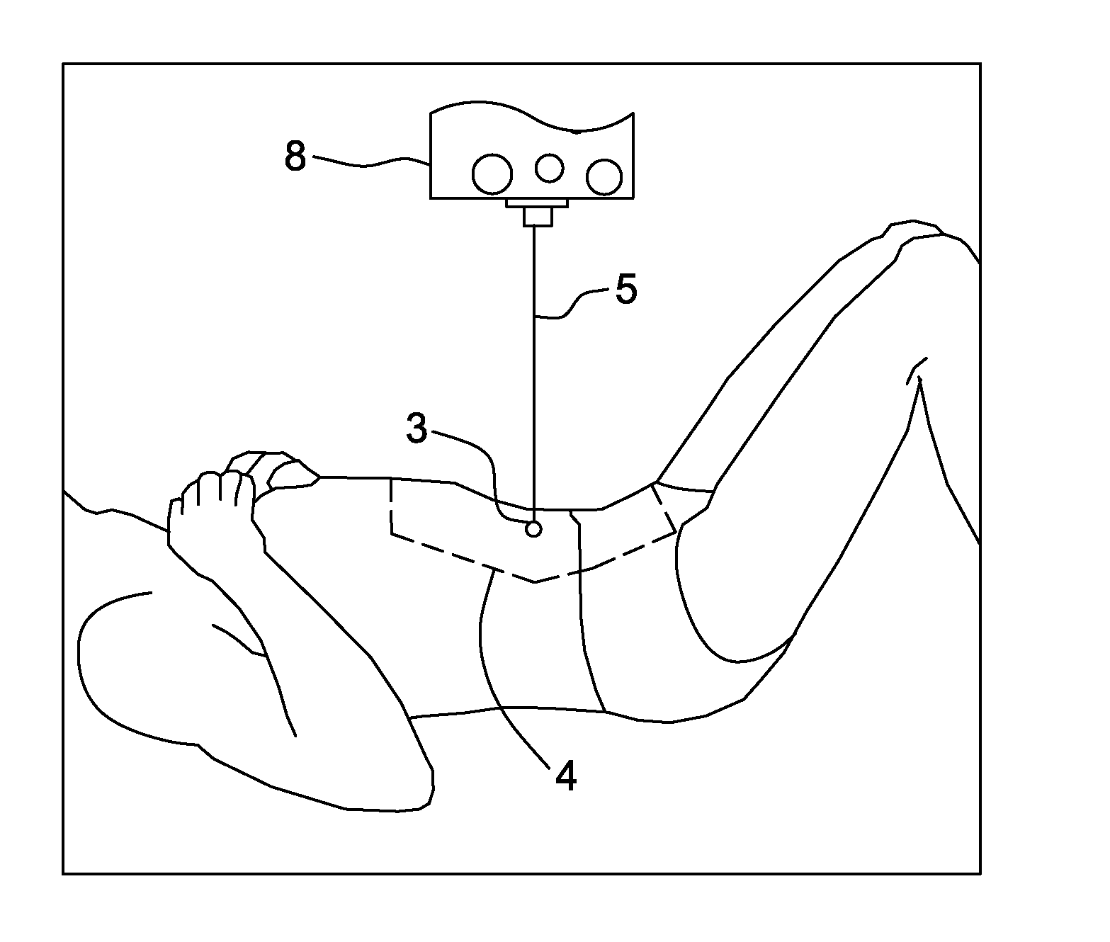
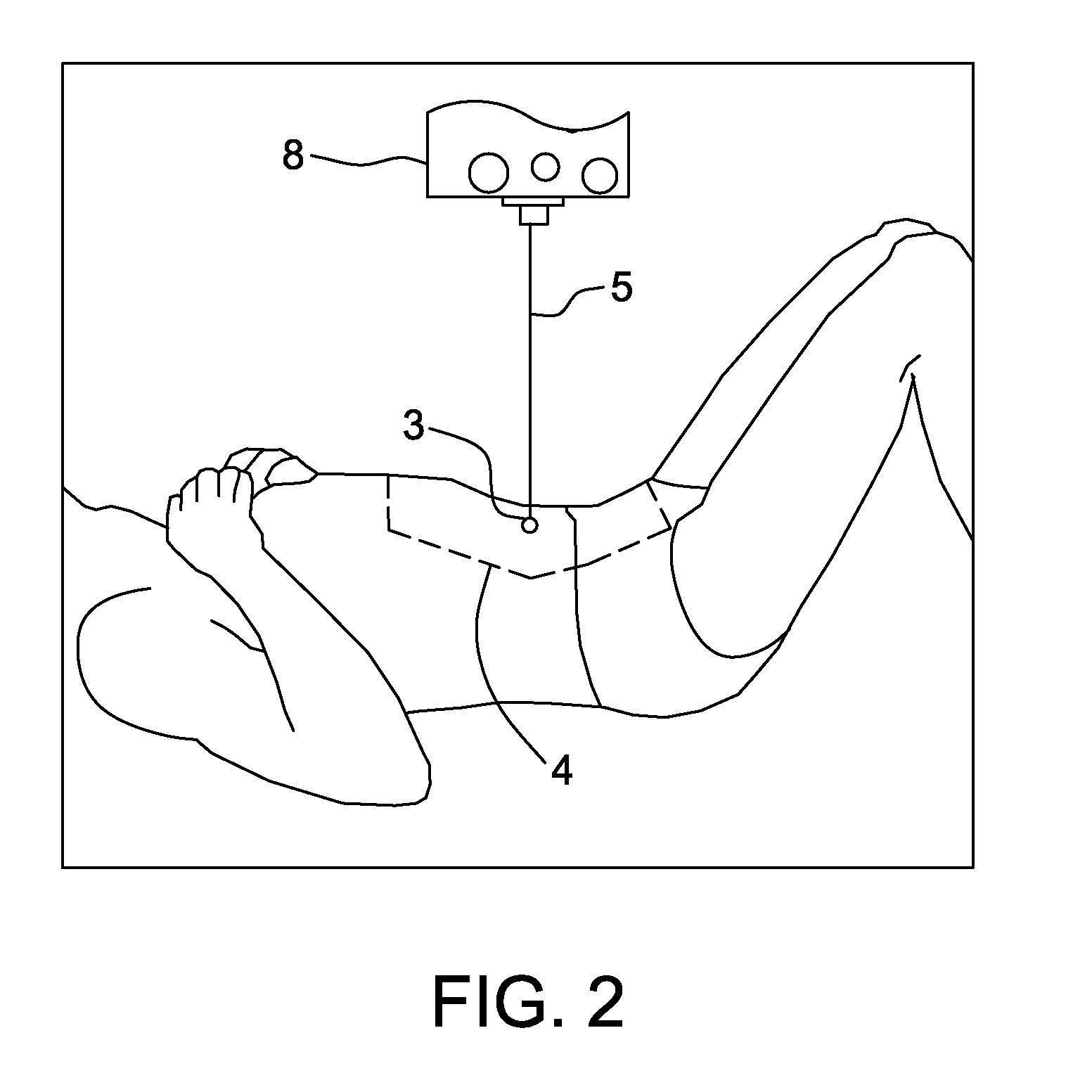
[0036]A preferred embodiment is a collimation system for a medical apparatus, particularly such as an X-ray diagnosis apparatus, as shown in FIG. 3. The medical apparatus (i.e. the X-ray diagnosis apparatus) itself is not shown. A laser emitting device in the collimation component is a hand-held laser pulse emission pen (1) with a button thereon for controlling emission of laser pulses. An operator holds the laser pulse emission pen, presses the button to continuously emit laser pulses, and directs the laser pulses toward an irradiation landmark on the body surface of a patient. The ...


PUM


Abstract

A collimation system for a medical apparatus includes a collimation component having a laser emitting device, at least one photographing device, and a computing device. The laser emitting device is configured to the emit a laser beam to irradiate on a landmark on a body surface of a patient, the at least one photographing device is configured to take a photograph of a laser irradiation spot, and the computing device is configured to obtain a position of the laser irradiation spot by performing computation on images obtained by the at least one photographing device. The system further includes a moving component provided on the medical apparatus and configured to move to a target position for performing diagnosis or treatment. The medical apparatus automatically is configured to locate the moving component based on the position of the irradiation spot obtained from the computation.

Description

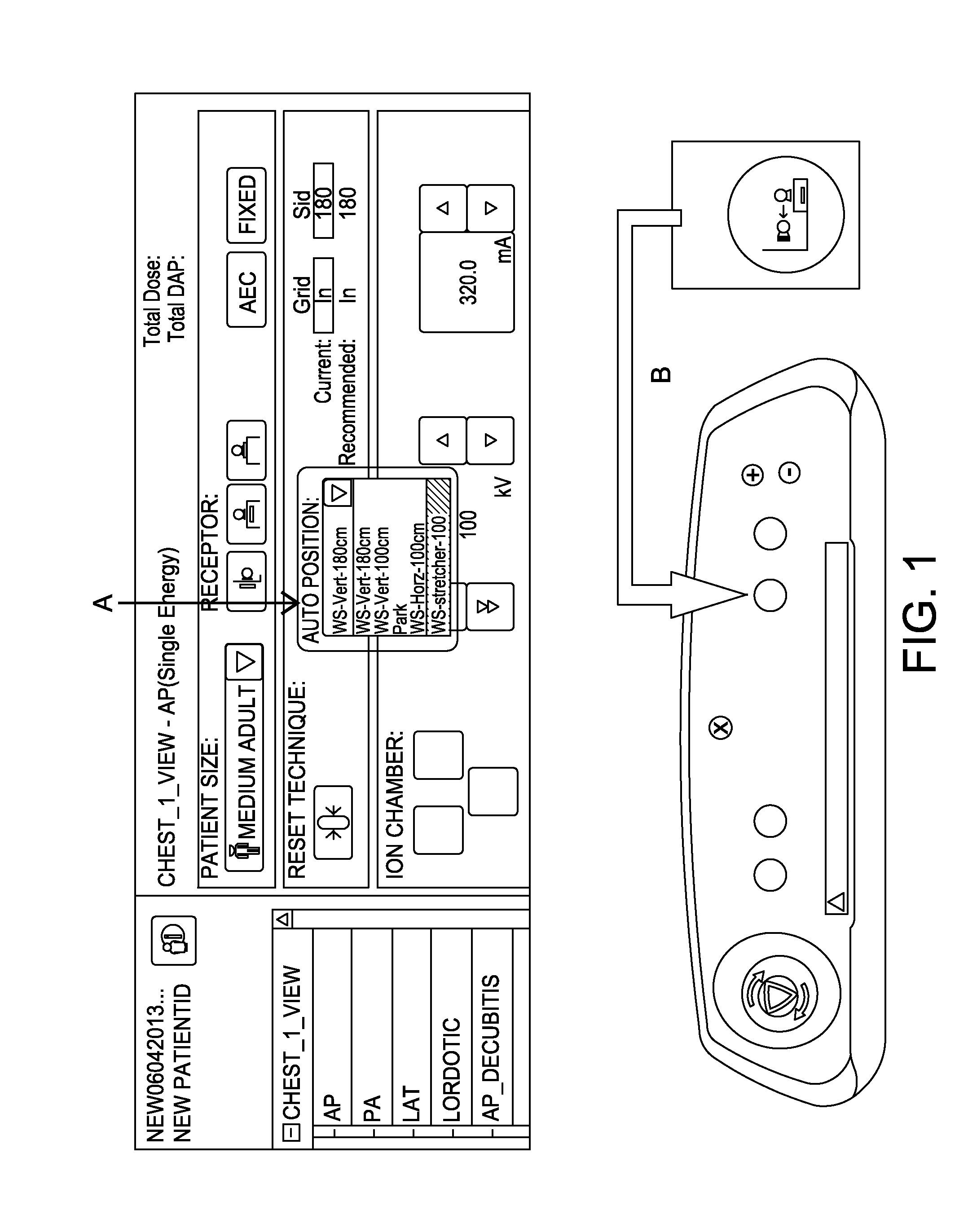
CROSS REFERENCE TO RELATED APPLICATIONS[0001]This application claims the benefit of Chinese Patent Application No. 201010552002.3 filed Nov. 9, 2010, which is hereby incorporated by reference in its entirety.BACKGROUND OF THE INVENTION[0002]The present application relates to the field of medical apparatus including medical imaging apparatus and treatment system, particularly to an X-ray apparatus and system; and relates to the collimation of the position of the body of a patient through collimation of an irradiation landmark on the body surface of the patient.[0003]Radiography usually requires precise collimation of a particular position on the body surface of a patient. Precise and fast collimation is the key point of successful irradiation and helps to reduce the time of the whole irradiation process and to decrease patient discomfort.[0004]Currently, the procedure of collimating a patient of a digital radiography system with automatic collimation function (such as a GE Definium 8...

Claims


Application Information

Patent Timeline
IPC IPC(8): A61B18/20
CPCA61B6/08A61B6/0492
Inventor JIA, LEILIN, LIN
Owner GENERAL ELECTRIC CO
Learn More