Safety controller and method for controlling an automated installation

a safety controller and automation technology, applied in the direction of program control, total factory control, instruments, etc., can solve the problems of limiting the flexibility of hardware implementation, affecting the operation of safety controllers, so as to reduce the response time of safety controllers, reduce the cost of implementation, and improve the flexibility of safety controllers

Active Publication Date: 2012-05-10
PILZ (COMPANY)
View PDF13 Cites 2 Cited by
  • Summary
  • Abstract
  • Description
  • Claims
  • Application Information

AI Technical Summary

Benefits of technology

[0009]It is an object of the present invention, therefore, to provide a safety controller and a method of the type initially mentioned in order to reduce the response time of a safety controller and, at the same time, to reduce the cost for implementing a safety controller in order to thus provide for a more rapid, more flexible safety controller optimized with regard to its availability.

Problems solved by technology

Therefore, extremely high requirements are placed on the inherent failsafety of safety controllers which leads to a considerable outlay for development and production.
With regard to programming or software-related implementation and thus the concerns of data processing, distributed safety controllers are not yet optimal, however.
This not only restricts the flexibility possible with regard to the hardware implementation to a considerable extent but also entails further disadvantages.
Due to the fact that the project data cannot be distributed and thus processed “on site”, a considerable data exchange is required between distant controller hardware components.
This leads to an impairment, more precisely to an increase in the response time of the safety controller.
This increases the cost for implementing a safety controller.
With respect to the cost, it is also of disadvantage that any free memory which may be present, especially data memory, in individual controller hardware components, such as in intelligent sensors and intelligent actuators, is not used and, instead, the data memory contained in control units must be dimensioned to be larger than would actually be required.

Method used


Image

  • Safety controller and method for controlling an automated installation
  • Safety controller and method for controlling an automated installation
  • Safety controller and method for controlling an automated installation

Examples


Embodiment Construction

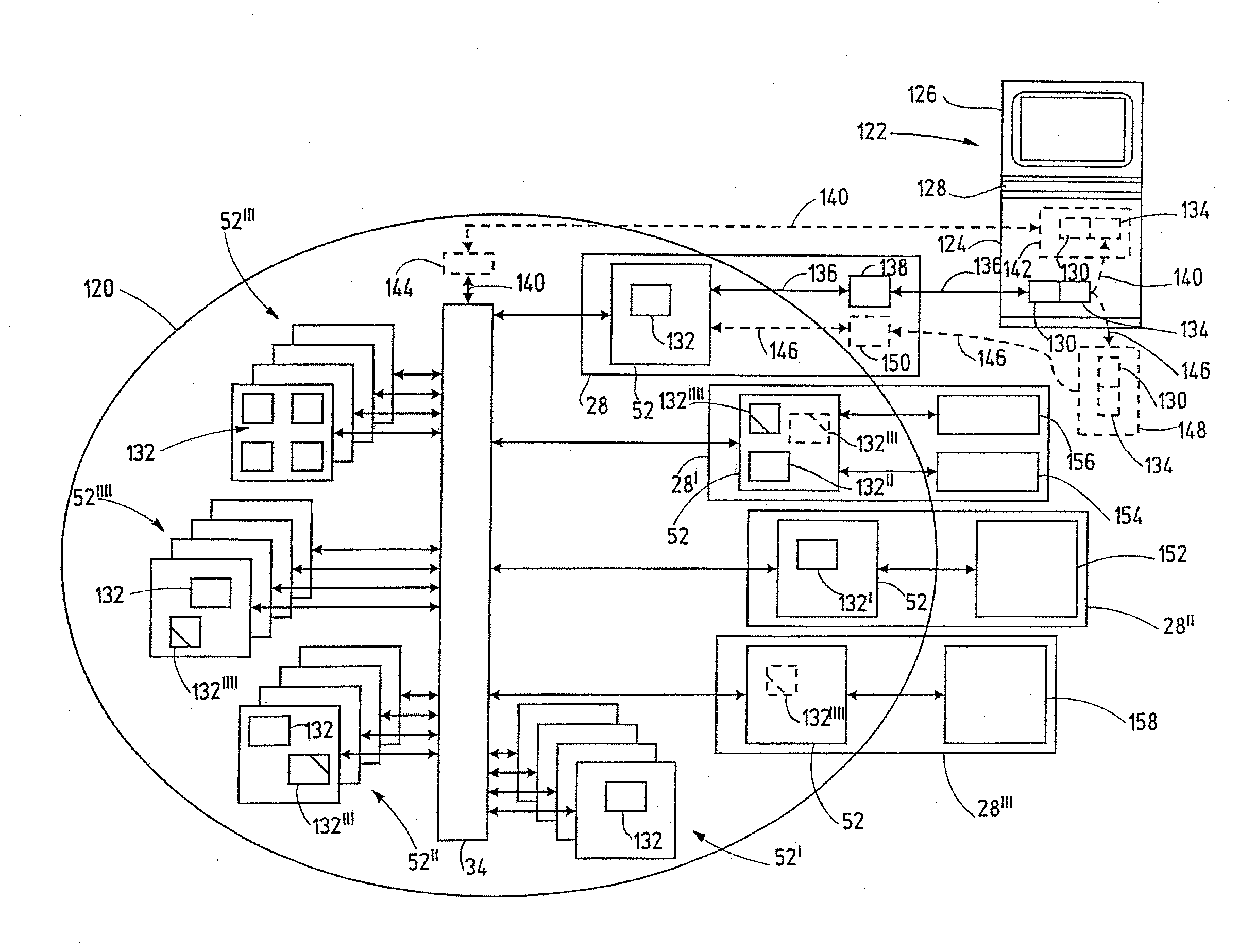
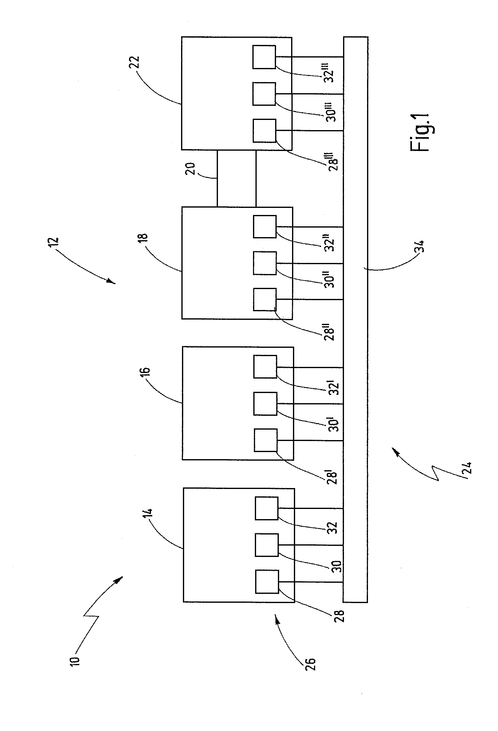
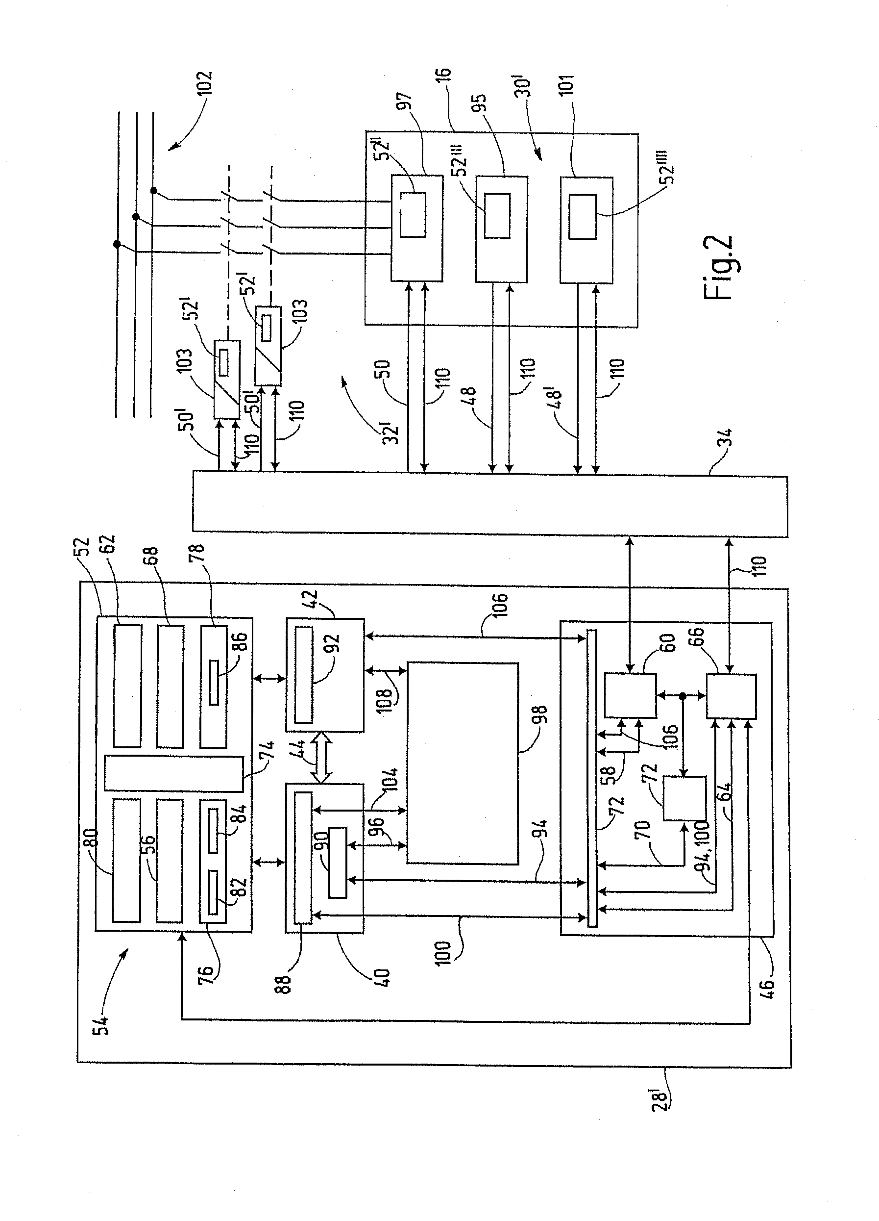
[0055]In FIG. 1, a installation to be controlled is designated in its entirety by reference number 10. The installation 10 comprises a plurality of installation hardware components 12. In the present exemplary embodiment, there is a placement station 14, a processing station 16, a test station 18, a conveying unit 20 and a packing and palletizing station 22. Furthermore, a safety controller is designated by the reference number 24 in its entirety. The safety controller 24 contains a plurality of controller hardware components 26. The controller hardware components 26 are control units 28, sensors 30 and actuators 32. In this context, the individual control units 28, sensors 30 and individual actuators 32 are in each case allocated to one of the installation hardware components 12 and are spatially arranged there. The controller hardware components 12 are connected to one another via a connecting unit 34. The connecting unit 34 is a data bus which, for example, is designed as Etherne...


PUM


Abstract

A safety controller controls an automated installation on the basis of project data representing an individual application running. The safety controller has a plurality of controller hardware components. At least some controller hardware components have a respective project data memory. The project data memories each are designed to store project data supplied to them. The safety controller includes a connecting unit, such as a communication network, which connects the controller hardware components to one another. The safety controller also has a distribution unit for distributing at least some of the project data via the connecting unit to at least some of the project data memories.

Description

CROSSREFERENCES TO RELATED APPLICATIONS[0001]This application is a continuation of international patent application PCT / EP2010 / 002438 filed on Apr. 20, 2010 designating the U.S., which international patent application has been published in German language and claims priority from German patent application DE 10 2009 019 096.1 filed on Apr. 20, 2009. The entire contents of these priority applications are incorporated herein by reference.BACKGROUND OF THE INVENTION[0002]The present invention relates to a safety controller and to a method for controlling an automated installation based on project data, wherein the project data represent an application running on the installation.[0003]A safety controller in terms of the present invention is an apparatus or a device which receives input signals supplied by sensors and generates output signals from these input signals by means of logical combinations and possibly further signal or data processing steps. The output signals can then be sup...

Claims


Application Information

Patent Timeline
Patent Type & Authority Applications(United States)
IPC IPC(8): G05B9/02
CPCG05B19/41865G05B2219/33338G05B2219/33273G05B2219/32283Y02P90/02
Inventor REUSCH, MATTHIASPETZOLD, KARSTENKLING, MICHAELSCHIPS, PATRICKBANZHAF, BERNDSTANKO, FLORIANWALTER, HERBERTNAWRATIL, TIMO
Owner PILZ (COMPANY)
Why Eureka
Try Eureka