Vacuum Chromatography Gas Detector

a vacuum chromatograph and gas detector technology, applied in the vacuum field, can solve the problems of potential fire hazards, large cylinders, and large dimensional dimensions of typical laboratory gas chromatographs employed in the laboratory setting

Inactive Publication Date: 2012-05-17
MEADOWORKS
View PDF5 Cites 18 Cited by
  • Summary
  • Abstract
  • Description
  • Claims
  • Application Information

AI Technical Summary

Benefits of technology

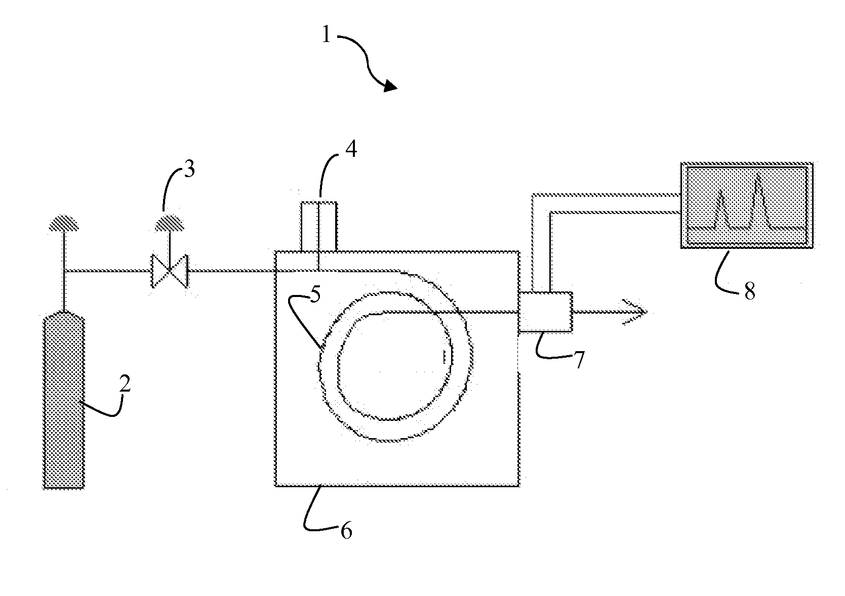
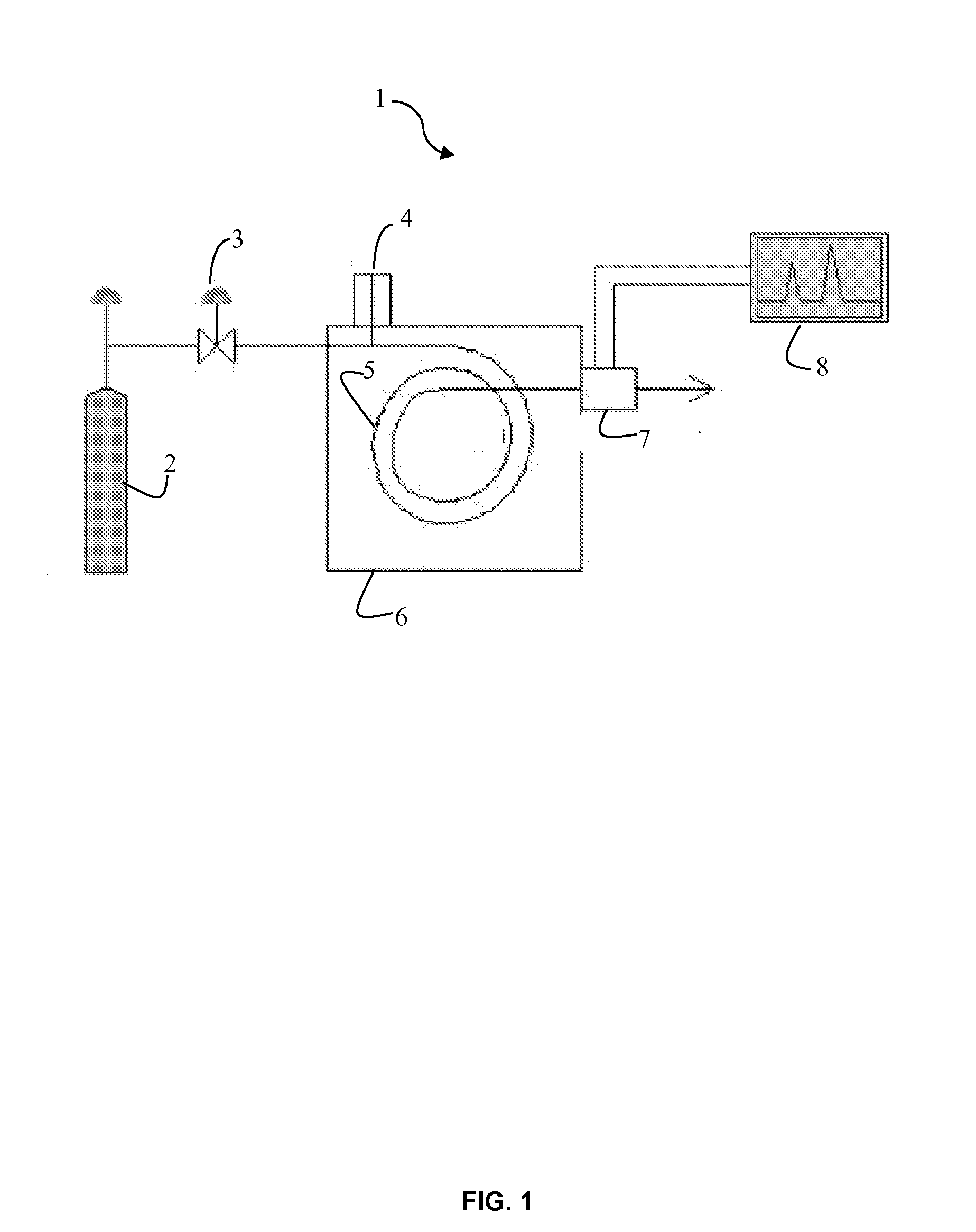
[0018]A first embodiment of the present invention is directed to a portable gas chromatograph comprising a solenoid valve for permitting a gaseous sample to pass through a separator column in fluid communication with the solenoid valve, a sample component detector in fluid communication with the separator column, the sample component detector to detect constituent components of the gaseous sample as they emerge from the separation column, at least one of a vacuum chamber in fluid communication with the sample component detector and a vacuum pump in fluid communication with the vacuum chamber, and a controller. The controller of that embodiment includes a first input coupled to the sample component detector, a first output coupled to the solenoid valve, a second output coupled to the vacuum pump, and a processor coupled to the first input, first output, and second output. The processor includes instructions which, when executed by the processor, cause the processor to control operation of the solenoid valve, and control operation of the vacuum pump.

Problems solved by technology

However, typical gas chromatographs employed in the laboratory setting are dimensionally large, heavy and are not easily transported for use in the field.
Such cylinders are also large and heavy, and the stored gas is under high pressure which poses a potential fire hazard for certain gases, i.e. hydrogen.
An additional disadvantage of current gas chromatographs is that they require significant analysis times. Such time requirements are imposed due to several factors.
First, the use of long separation columns, i.e. greater than 50 meters, increases the time necessary for materials of interest to traverse the entire column.
Second, the process of complete separation is significantly increased for some samples due to the presence of relativity high boiling point components which travel very slowly along the separation column.

Method used


Image

  • Vacuum Chromatography Gas Detector
  • Vacuum Chromatography Gas Detector
  • Vacuum Chromatography Gas Detector

Examples


Embodiment Construction

[0040]In the following description, the present invention is set forth in the context of various alternative embodiments and implementations involving a portable gas chromatography system and method for the rapid detection of chemical and / or biological agents in air samples. It will be appreciated that these embodiments and implementations are illustrative and various aspects of the invention may have applicability beyond the specifically described contexts. Furthermore, it is to be understood that these embodiments and implementations are not limited to the particular compositions, methodologies, or protocols described, as these may vary. The terminology used in the following description is for the purpose of illustrating the particular versions or embodiments only, and is not intended to limit their scope in the present disclosure which will be limited only by the appended claims.

[0041]Throughout the specification, reference to “one embodiment,”“an embodiment,” or “some embodiment...


PUM

PropertyMeasurementUnit
diameteraaaaaaaaaa
lengthaaaaaaaaaa
diameteraaaaaaaaaa

Abstract

A portable gas chromatography system and method of use. The portable gas chromatograph may be used to accurately and rapidly detect low-level concentrations of chemicals, such as fixed gases, volatilized liquid samples, or toxic chemicals and transmit to a user data relating to the presence and identity of such. The portable gas chromatograph uses an onboard vacuum source to pull samples into and through the system and thus does not require the use of a carrier gas. Further, the system comprises a solenoid valve for capturing the sample and may include a short porous layer open tubular separation column, and a thermal conductivity detector. Overall size and weight of the system is small enough for a user to carry. The method of operation of the gas chromatograph includes taking rapid successive samples and analyzing the data outputs using Fourier transform techniques. Such analysis allows real-time data updates and rapid detection of hazardous environmental agents.

Description

CROSS-REFERENCE TO RELATED APPLICATIONS[0001]Not ApplicableSTATEMENT REGARDING FEDERALLY SPONSORED RESEARCH[0002]Not ApplicableTHE NAMES OF THE PARTIES TO A JOINT RESEARCH AGREEMENT[0003]Not ApplicableINCORPORATION-BY-REFERENCE OF MATERIAL ON DISC[0004]Not ApplicableBACKGROUND[0005]1. Technical Field of the Invention[0006]This invention pertains generally to a portable gas chromatography system and method which can accurately and rapidly detect low-level concentrations of fixed gases, volatilized liquid samples, or toxic chemicals and transmit to a user data relating to the presence and identity of such. More specifically, the disclosure contained herein provides a portable gas chromatography system which uses an onboard vacuum source to pull samples into and through the system and does not require the use of a carrier gas. Further, the disclosure provides a method for operation of the system which includes taking rapid successive samples and analyzing the data outputs using Fourier...

Claims


Application Information

Patent Timeline
Patent Type & Authority Applications(United States)
IPC IPC(8): B01D53/02G01N30/02
CPCG01N1/2214G01N1/2273G01N30/08G01N30/20G01N2033/0019G01N30/88G01N2001/248G01N2030/8881G01N30/24
Inventor CATES, MARION H.
Owner MEADOWORKS
Why Eureka
Try Eureka