High pressure injection system having fuel cooling from low pressure region

a high pressure injection and low pressure technology, applied in the direction of fuel injection apparatus, charge feed system, machine/engine, etc., can solve the problems of high temperature in the return, increase in fuel temperature, and need for more expensive materials, so as to achieve maximum freedom, short cooling line, and large volume flow

Inactive Publication Date: 2012-05-17
ROBERT BOSCH GMBH
View PDF60 Cites 1 Cited by
  • Summary
  • Abstract
  • Description
  • Claims
  • Application Information

AI Technical Summary

Benefits of technology

[0005]The invention makes it possible to reduce the disadvantages of an uncooled fuel return by simple and inexpensive means. For this purpose, a cooling line for adding fuel from cooler regions of the low pressure region is provided between the fuel tank and the high pressure pump, enabling cooler fuel to be added to the fuel return. As a result, the fuel temperature in the return is reduced and the abovementioned negative effects thus no longer occur or at least occur only to a significantly reduced extent.
[0006]A first illustrative embodiment of the fuel injection system is characterized in that the cooling line receives a volume flow required for fuel cooling between a fuel feed pump and the high pressure pump and feeds this volume flow to the leakage flow from the fuel injection valves, which can be embodied as common rail injectors for example, via a mixing point for the purpose of cooling. The fuel feed pump ensures that there is a volume flow at sufficient pressure for cooling purposes at all times and therefore this embodiment does not require additional regulating mechanisms. Another advantage of this embodiment is that the fuel feed pump eliminates the need for a pre-feed pump at the high pressure pump.
[0007]Another illustrative embodiment of the fuel injection system is characterized in that the cooling line receives a volume flow required for fuel cooling from the pre-feed pump arranged at the high pressure pump and feeds this volume flow to the leakage flow from the fuel injection valves via a mixing point. The pre-feed pump directly at the high pressure pump, which can be embodied as a gear pump for example, which draws in a volume flow from the fuel tank, eliminates the need for the fuel feed pump. The advantage of this embodiment is that the cooling line can be made correspondingly short and thus inexpensive.

Problems solved by technology

The compression of the fuel in the high pressure pump leads to a rise in the fuel temperature.
Moreover, the increased return temperatures may necessitate more expensive materials for the embodiment of the return lines.
In the injection system known, for example, from DE 10 2004 037 557 A1, the fuel is returned to the fuel tank without cooling, and this leads to a high temperature in the return.
This necessitates correspondingly high-grade and expensive materials for the return lines and, under some circumstances, may lead to decomposition of the fuel, resulting in increased wear in the high pressure injection system.
KR-717316 B1 has disclosed high pressure injection systems with a separate cooling apparatus in the fuel return, but these lead to a large amount of additional design effort and to corresponding additional costs and, owing to their design, require a relatively large amount of installation space, the result being that such a solution cannot be implemented at every desired location in the engine compartment or leads to expensive redesign in the engine compartment.

Method used


Image

  • High pressure injection system having fuel cooling from low pressure region
  • High pressure injection system having fuel cooling from low pressure region
  • High pressure injection system having fuel cooling from low pressure region

Examples


Embodiment Construction

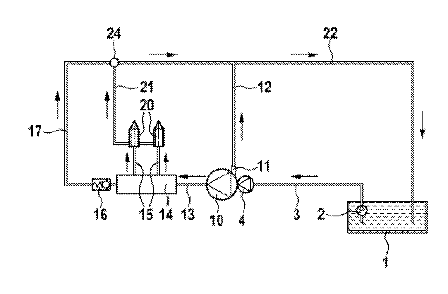
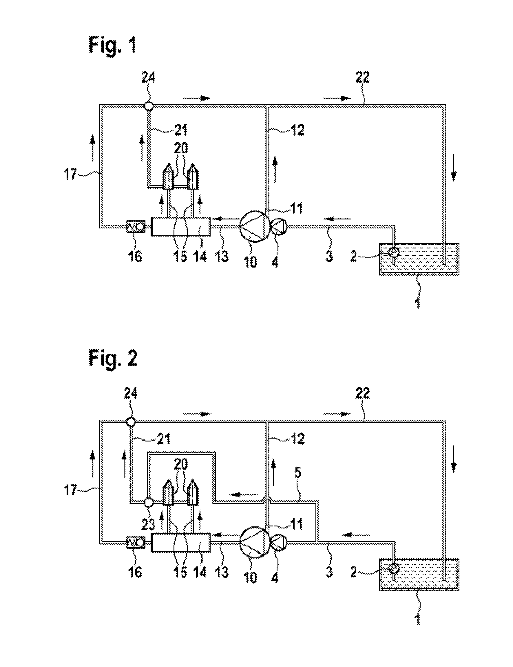
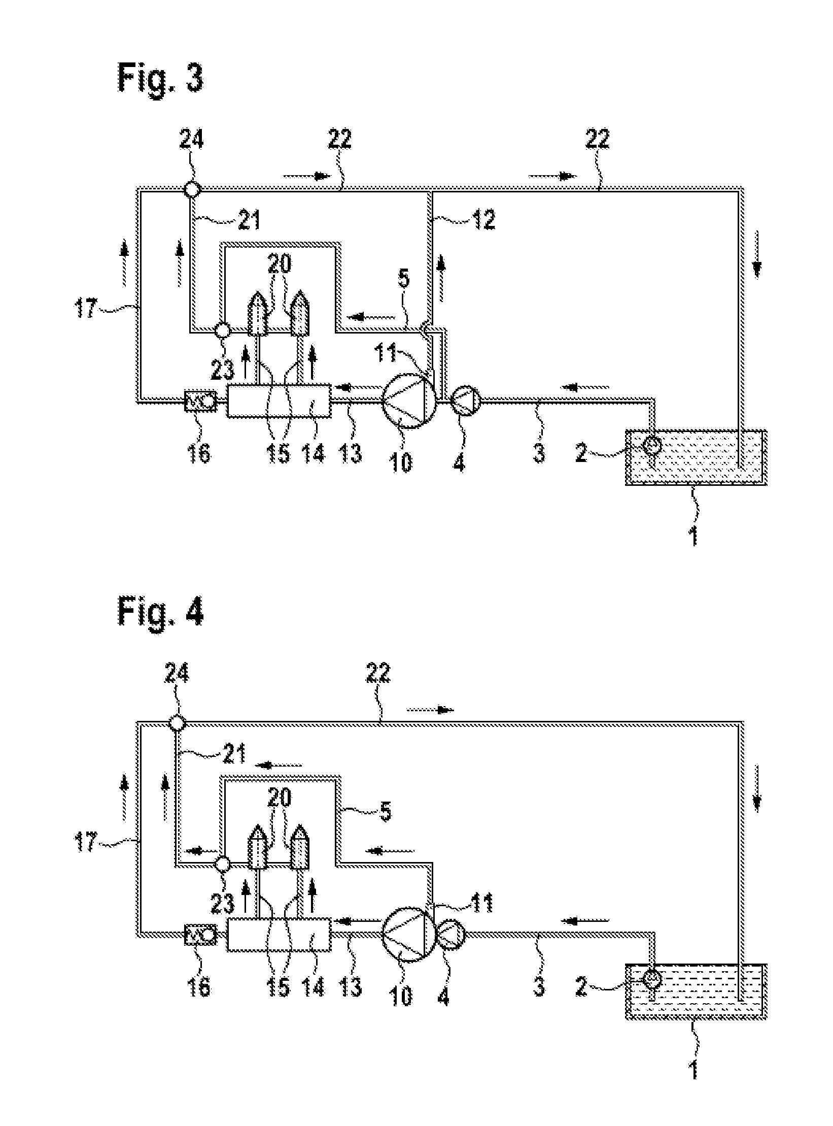
[0018]A high pressure injection system known from the prior art is illustrated schematically in FIG. 1. Fuel is fed from a fuel tank 1 to a pre-feed pump 4 and to a high pressure pump 10 via a connection line 3 by means of a fuel feed pump 2. The fuel tank 1, the fuel feed pump 2, the connection line 3 and the pre-feed pump 4 are subjected to low pressure and are therefore assigned to the low pressure region.

[0019]Arranged at the high pressure pump 10 is a fuel return 11, which is connected to the fuel tank 1 by a return line 12 and a further return line 22. Also leading away from the high pressure pump 10 is a high pressure line 13 to a high pressure reservoir 14, also referred to as a common rail, which is connected to the fuel injection valves 20 by further high pressure lines 15. The presence of a high pressure reservoir 14 is not absolutely essential here.

[0020]To operate an internal combustion engine (not shown), the fuel compressed by the high pressure pump 10 is injected int...


PUM


Abstract

The invention relates to a high pressure injection system having a fuel tank, a connection line between the fuel tank and a high pressure pump for sealing the fuel, wherein the high pressure pump is connected to at least one fuel injection valve via a corresponding connection line. According to the invention, at least a partial volume of the fuel sealed in the high pressure pump is fed back to the fuel tank from said fuel injection valve by leakage in the fuel injection valve via a return line connected to the fuel tank. An essential characteristic of the invention is that the high pressure injection system comprises a cooling line that connects the fuel tank or the low pressure region to the high pressure or a return of the high pressure pump via a mixing point with the return line. It is thereby possible to cool the fuel in the return lines between the fuel injection valve and the fuel tank.

Description

BACKGROUND OF THE INVENTION[0001]The invention relates to a high pressure injection system, in particular to a high pressure reservoir injection system for internal combustion engines, having a fuel tank, from which the fuel is fed to the high pressure pump by means of a fuel feed pump and a line system. The compression of the fuel in the high pressure pump leads to a rise in the fuel temperature. The compressed fuel is fed through a further line by the high pressure pump into a high pressure reservoir, which, for its part, is connected at least to a fuel injection valve. During the operation of the internal combustion engine, compressed fuel is injected from the fuel injection valve into a combustion chamber. Part of the fuel fed to the fuel injection valve passes out of the fuel injection valve into the return line owing to leakage in the fuel injection valve or as a control quantity, wherein said leakage quantities are additionally heated through the relief of pressure as they fl...

Claims


Application Information

Patent Timeline
Patent Type & Authority Applications(United States)
IPC IPC(8): F02M53/04F02M59/20
CPCF02M53/00F02M63/0225F02M55/002
Inventor SPINDLER, SUSANNEWALTHER, JOCHENSOMMER, DOROTHEEKIEFERLE, STEFAN
Owner ROBERT BOSCH GMBH
Why Eureka
Try Eureka