Seal lip on vane
- Summary
- Abstract
- Description
- Claims
- Application Information
AI Technical Summary
Benefits of technology
Problems solved by technology
Method used
Image

Examples
first embodiment
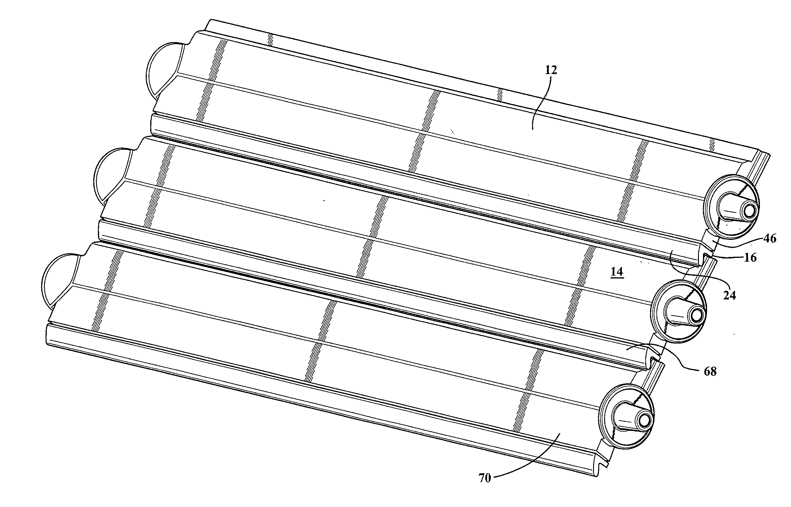
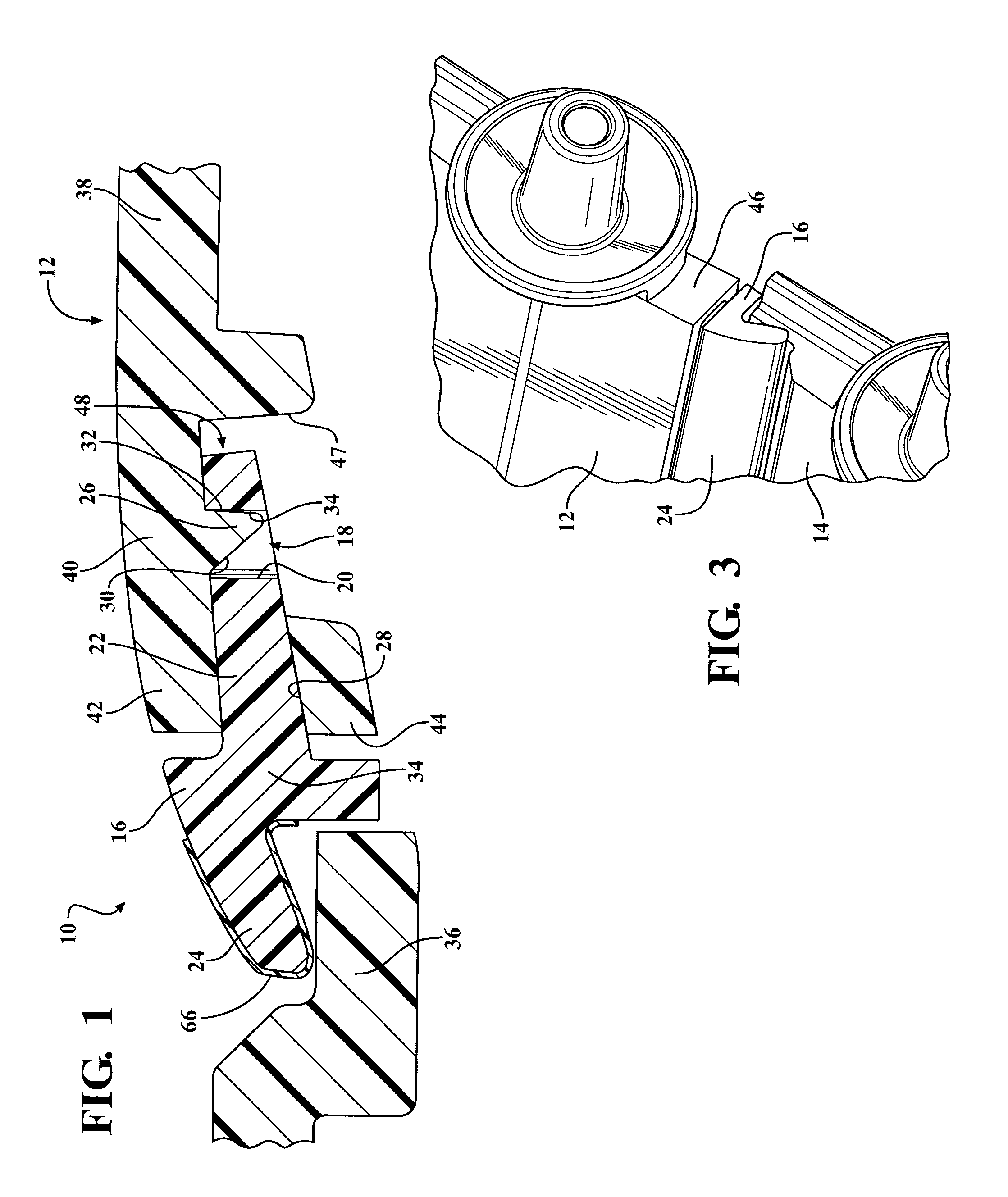
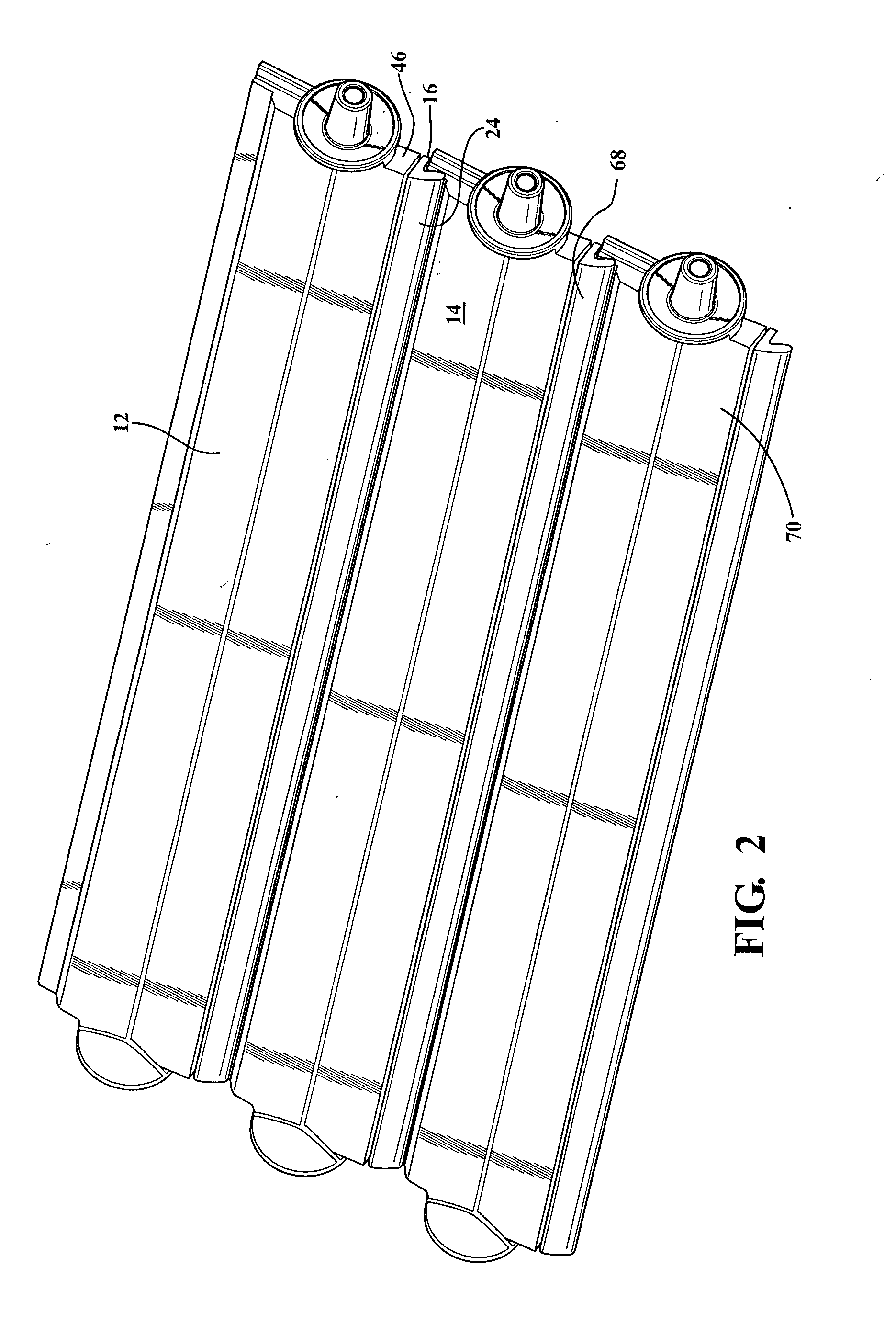
[0031]the present invention is shown in FIGS. 1-4 and 8C-8D. More specifically, a louver or vane having a seal with a retention feature according to the present invention is shown generally at 10. There is a first louver, shown generally at 12, and a second louver, shown generally at 14, which are adjacent one another and make up a system of louvers used for controlling the flow of air through an engine compartment of a vehicle. While the present embodiment describes two louvers 12,14, it is within the scope of the invention that the system of louvers may have more than two louvers.
[0032]Attached to the first louver 12 is a first seal 16, which is connected to the first louver 12 through a retention feature, generally shown at 18. The retention feature 18 includes a first aperture 20 formed as part of a base portion 22 of the seal 16. The seal 16 also includes a lip 24 for selectively contacting the second louver 14, best seen in FIG. 1. Also formed as part of the retention feature ...
third embodiment
[0038]In a third embodiment, shown in FIGS. 7-8B, the seal 16 has the lip 24 and body portion 34, but the seal 16 does not include the base portion 22. In this embodiment, the retention feature 18 includes a groove, shown generally at 50, formed as part of the seal 16, and the groove 50 is operable to retain the louver 14. The louver 14 slides into the groove 50 during assembly. The front portion 40 has a retaining flange 52 which is substantially perpendicular to an extension 54, generally forming a T-shape, and the retaining flange 52 and extension 54 are also part of the retention feature 18 in this embodiment. The groove 50 of the seal 16 in this embodiment has a general C-shape, which corresponds to the T-shape created by the flange 52 and the extension 54. The retaining flange 52 has an upper rear surface 56 and a lower rear surface 58. The groove 50 includes an upper backing surface 60 and a lower backing surface 62. When assembled, the upper backing surface 60 is in contact ...
fifth embodiment
[0042]the present invention is shown in FIGS. 10A-11B. The fifth embodiment is similar to the first embodiment, with like numbers referring to like elements. In this embodiment, however, the flange 26 is formed as part of the base portion 22, and extends into the aperture 47 when the seal 16 is attached to the louver 12, preventing the seal, 16 from being detached from the louver 12. Also formed as part of the upper flange 42 of the louver 12 is a detent feature 72 which as seen in FIG. 10A contacts the base portion 22, and provides positioning of the seal 16 relative to the louver 12.
[0043]In each of the embodiments described above, the seal 16 also may include a slip coat 66 which reduces friction between the seal 16 and the adjacent louver 14, or adjacent seal 16 if the adjacent louver 14 also includes a seal 16. The slip coat 66 may be extruded along with the seal 16, or may be applied to the seal 16 as part of a separate operation.
[0044]As mentioned above, there is a first louv...
PUM
 Abstract
Description
Claims
Application Information