Visualizing surgical trajectories

a surgical path and path technology, applied in the field of visualizing surgical paths, can solve problems such as surgeons not being able to recognize, and achieve the effect of avoiding damag

Active Publication Date: 2012-05-17
KONINKLIJKE PHILIPS ELECTRONICS NV
View PDF7 Cites 25 Cited by
  • Summary
  • Abstract
  • Description
  • Claims
  • Application Information

AI Technical Summary

Benefits of technology

[0005]It is an object of the invention to provide a method of visualizing a surgical path as described in the opening paragraph, which method makes it easier to avoid damage of critical anatomical structures.

Problems solved by technology

If the prior art system finds a path which does not intersect any structure but comes very close to a critical anatomical structure, the surgeon will not recognize that.

Method used


Image

  • Visualizing surgical trajectories
  • Visualizing surgical trajectories
  • Visualizing surgical trajectories

Examples


Embodiment Construction

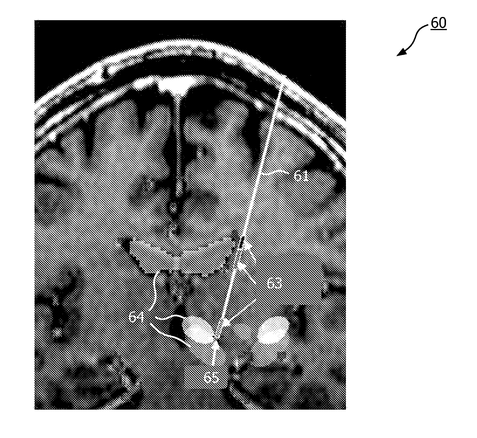
[0026]In the following, the invention will be described by an exemplary embodiment related to neurosurgery using electrophysiological probes. The invention is however not limited to use with a neuro-EP system. Other surgical interventions where knowledge about anatomic information along a surgical trajectory (planned and / or navigated) is useful for clinical and / or diagnostic purposes may benefit as well from this invention. The invention may, e.g., be suitable for optical-needle guided interventions.

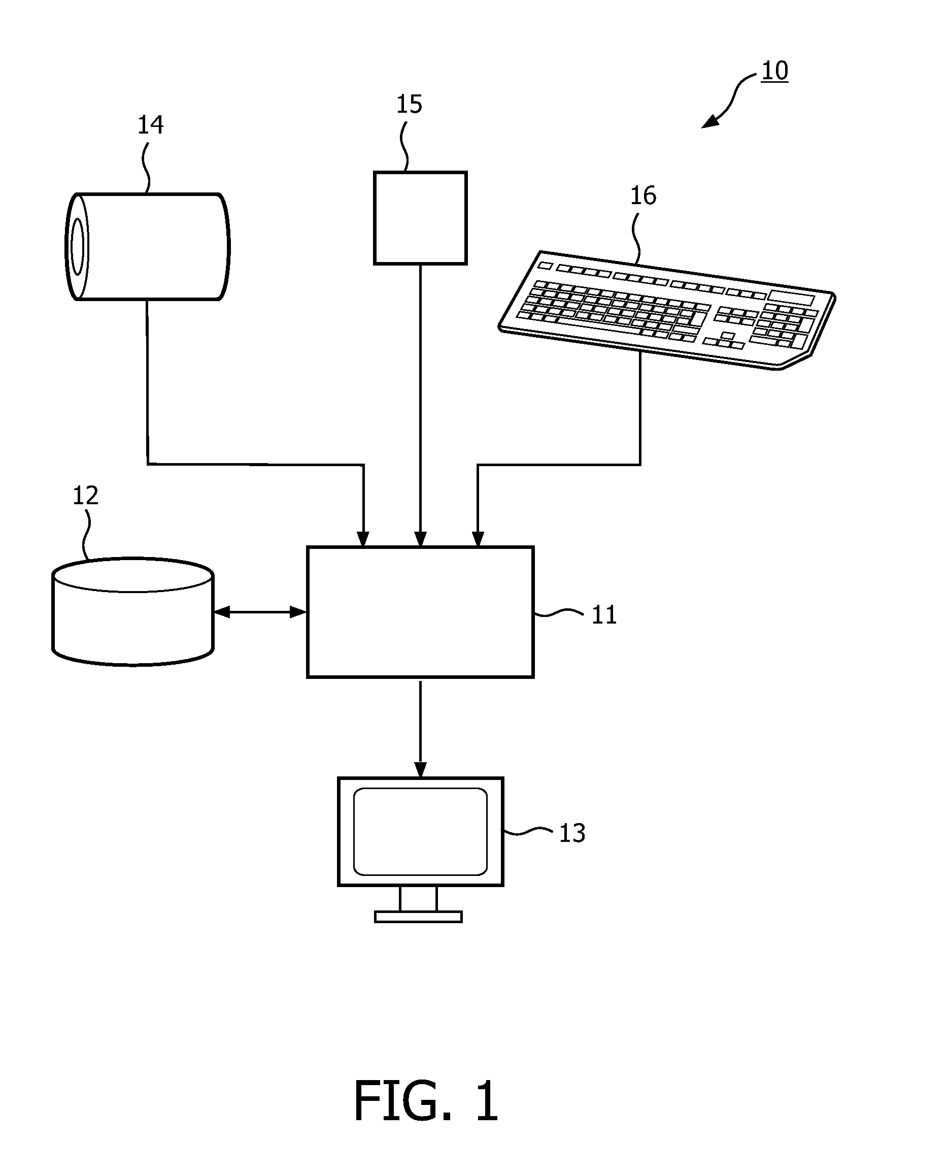
[0027]FIG. 1 schematically shows a system 10 for visualizing a surgical path according to the invention. The system 10 comprises a processor 11 for receiving and processing all input data and providing a graphical representation of the surgical path as output data to a display 13. Input data, process parameters and output data may be stored on a memory 12. The processor 11, display 13 and memory 12 may together be part of one computer or may be separate items or parts of separate items. ...


PUM


Abstract

A method and system are provided for visualizing a surgical path (31, 41, 51) for a surgical tool. The method comprises a step of receiving (21) anatomical information (14) about a position of at least one anatomical structure (32, 33, 34, 35) in a region to undergo surgery, geometric information (15) describing the surgical path (31, 41, 51) and at least one safety margin defining a minimal distance between the surgical tool and the anatomical structure (32, 33, 34, 35). The method further comprises defining (23) a critical segment (43, 44, 45) of the surgical path (31, 41, 51), in which critical segment (43, 44, 45) a distance to the anatomical structure (32, 33, 34, 35) is smaller than the safety margin. Then a graphical representation (30, 40, 50) of the surgical path (31, 41, 51) is provided (24), wherein the critical segment (43, 44, 45) is highlighted.

Description

FIELD OF THE INVENTION[0001]This invention relates to a method of visualizing a surgical path for a surgical tool, the method comprising receiving anatomical information about a position of at least one anatomical structure in a region to undergo surgery and geometric information describing the surgical path.[0002]This invention further relates to a system and a computer program product for performing such a method.BACKGROUND OF THE INVENTION[0003]From United States patent application US 2007 / 0049861 A1 a system is known for automated planning of an access path for a minimally invasive intervention of an area of the body. 3D image data of the body area is processed and bones and elements endangered by the intervention are segmented. The image data is displayed and the user marks a target position in the image. The system then automatically determines one or more access paths to the target position which do not run through bones and which do not intersect any elements endangered by t...

Claims


Application Information

Patent Timeline
Patent Type & Authority Applications(United States)
IPC IPC(8): G09G5/02
CPCA61B19/20A61B2019/507A61B19/5244A61B19/50A61B90/10A61B34/10A61B34/20A61B2034/107
Inventor KOUDIJS, JOHANNES CORNELISBERGTHOLDT, MARTINSCHULZ, HEINRICHMARTENS, HUBERT CECILE FRANCOISBLOEM, GERRIT-JANKLEIBEUKER, JOHAN GERARD
Owner KONINKLIJKE PHILIPS ELECTRONICS NV
Why Eureka
Try Eureka