
Repeater and self-excitation detecting method and system

Inactive Publication Date: 2012-05-17
SHENZHEN GRENTECH CO LTD
View PDF7 Cites 15 Cited by
  • Summary
  • Abstract
  • Description
  • Claims
  • Application Information

AI Technical Summary

Benefits of technology

[0021]The self-excitation detecting method and system of the repeater and repeater specified in the embodiment of the invention possess the following advantages.
[0022]1. The self-excitation can be detected in time, thus avoiding bad effect on the communication system;
[0024]3. The cost incurred by the patrol inspection personnel can be reduced.

Problems solved by technology

The repeater, as an amplifying device, may cause a self-excitation if its engineering design is improper.
The self-excitation will exert an influence on the repeater and seriously affect the relevant base station, thereby resulting in that the whole communication system fails to work normally, which will affect the quality of communication and may further lead to the paralysis of the whole communication network.
However, this method involves the cost of manpower and instruments etc, and responds slowly due to the fact that the patrol inspection may not be at the right time.
Or the self-excitation is dealt with only when it has an effect on the operation of network, so customers become increasingly unsatisfied with this method.
However, this method is seldom put into operation because it may be subject to the limitation of geographic location or involve the increase in the cost of engineering design.
If the self-excitation occurs in the repeater, the signal of positive feedback can have a significant effect on local communication signals, and may burn down the devices in the repeater or even lead to the paralysis of communication system in case of a severe self-excitation.

Method used


Image

  • Repeater and self-excitation detecting method and system
  • Repeater and self-excitation detecting method and system
  • Repeater and self-excitation detecting method and system

Examples


Embodiment Construction

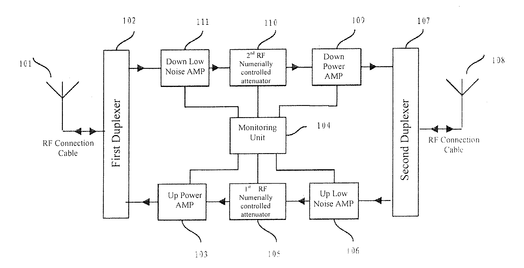
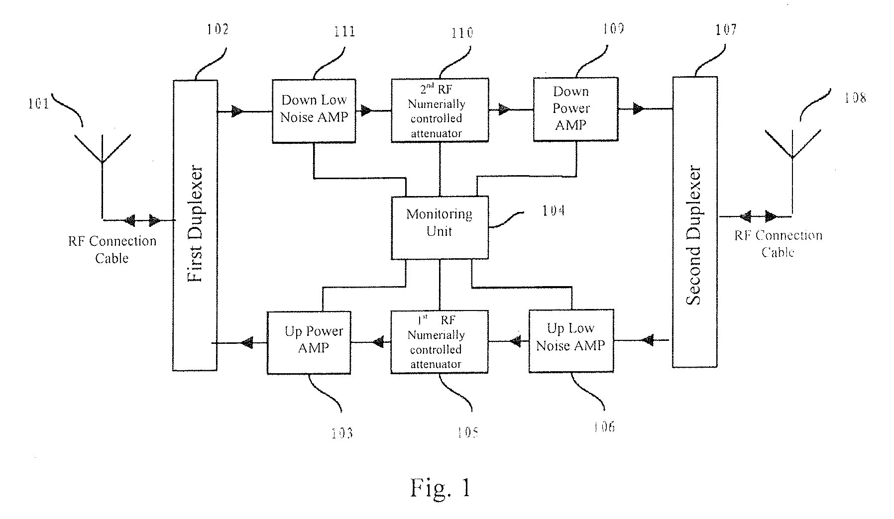
[0029]Considering the problems in the current technology, this inventor, based on the years of experience in the product design and engineering application, puts forward a kind of self-excitation detecting method, system and repeater on the basis of the current repeater.

[0030]The invention is described as follows with reference to the exemplary embodiments and the attached drawings.

[0031]Generally, the self-excitation is caused due to the fact that the isolation of signal (namely the inhibition of radio frequency signal) is less than the gain of repeater. The self-excitation of repeater may be generated in the up link and / or the down link. According to the practical engineering experience, the difference between the isolation of the up link and the down link is moderate. However, in order to keep balance between the up link and the down link in the communication system during engineering design, the difference between the actual gain of the up link and the down link is moderate too....


PUM


Abstract

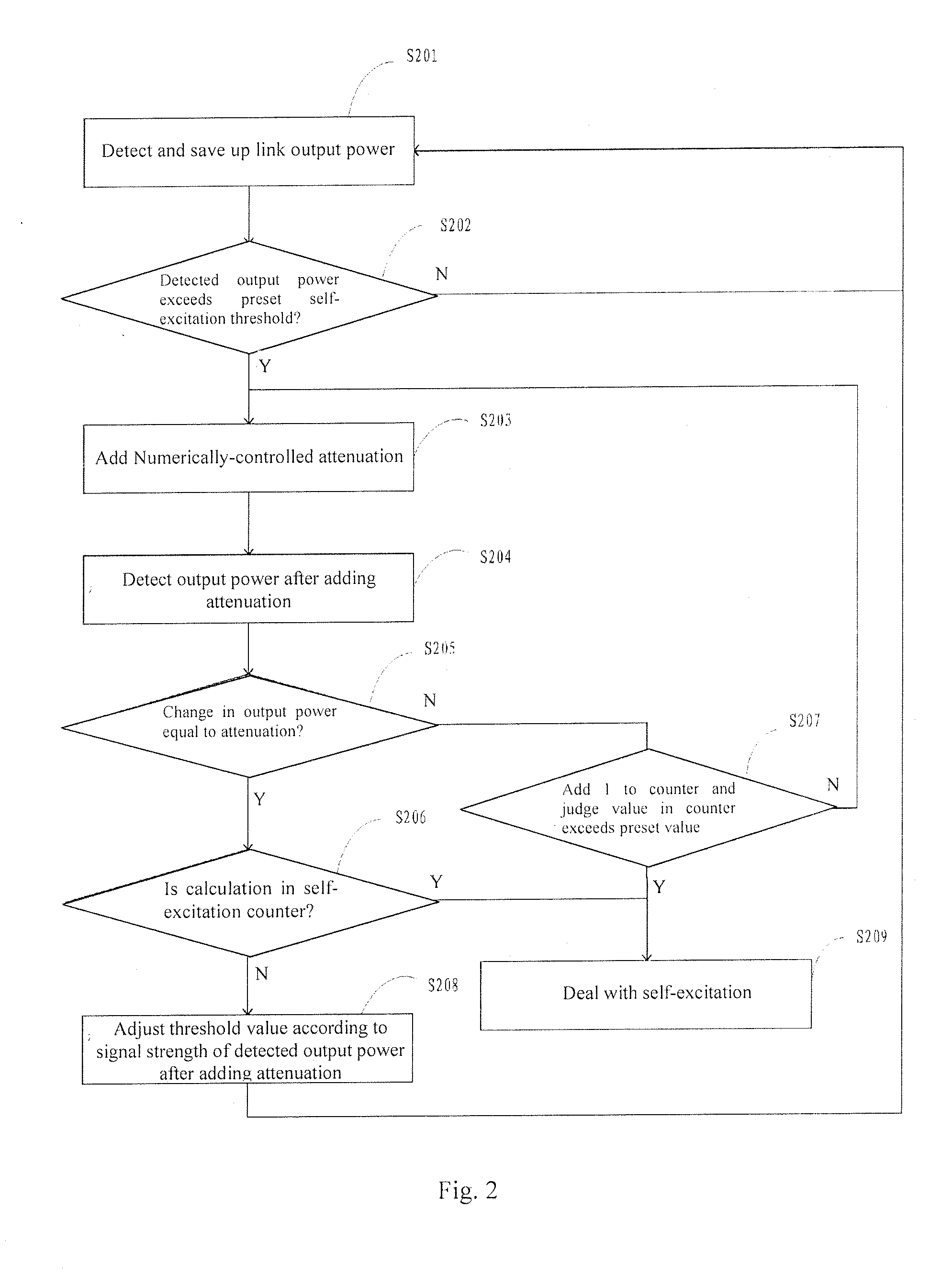
The present invention relates to the communication field and provides method and system for detecting repeater self-excitation and the repeater using the method and system. The method includes detecting an output power of an up link; judging whether the detected output power of the up link exceeds a threshold of self-excitation and, if so, adding a numerically-controlled attenuation to the up link accordingly; and judging whether the change in the output power of the up link is equal to that in the numerically-controlled attenuation and, judging whether the repeater is subject to a self-excitation according to the result of judgment regarding the change in the output power of the up link. The repeater self-excitation detecting method has the following advantages: 1. The self-excitation can be detected in time, thus avoiding had effect on the communication system; 2. The devices of repeater can be protected from being burned down; and 3. The cost incurred by the patrol inspection personnel can be reduced,

Description

BACKGROUND OF THE INVENTION[0001]1. Field of the Invention[0002]The present invention relates to the communication field and, more particularly, to a repeater and its self-excitation detecting method and system.[0003]2. Description of Related Art[0004]A repeater is an important component of the communication system and has a direct effect on the stability of the whole communication system. With the development of communication industry, the requirements for the repeater become stricter. The repeater, as an amplifying device, may cause a self-excitation if its engineering design is improper. The self-excitation will exert an influence on the repeater and seriously affect the relevant base station, thereby resulting in that the whole communication system fails to work normally, which will affect the quality of communication and may further lead to the paralysis of the whole communication network. Especially, CDMA system is more sensitive to the repeater self-excitation because it is a...

Claims


Application Information

Patent Timeline
IPC IPC(8): H04B3/36H04B17/40
CPCH04B17/40H04B7/155
Inventor LI, CHENGSHENGWANG, YALIDING, TIANWEN
Owner SHENZHEN GRENTECH CO LTD
Learn More