Embodiment 3
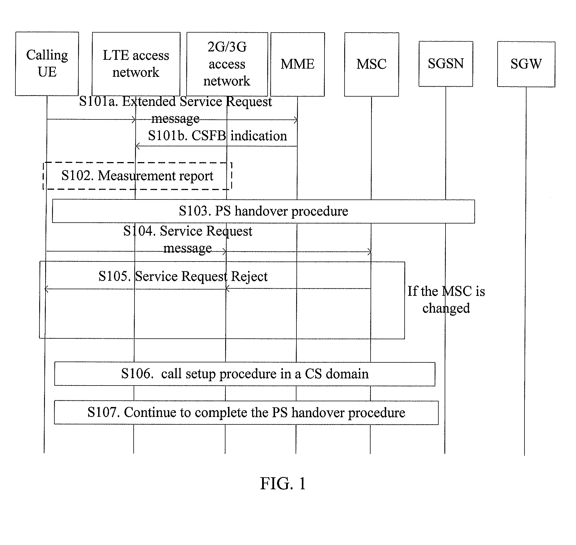
[0217]In this embodiment, a UE is a calling UE, and a 2G/3G network supports PS handover. The following describes the procedure for voice call fallback to a CS domain in a process where the UE initiates a call. As shown in FIG. 7, the specific steps are as follows:
[0218]S701a. A user wants to initiate a CS voice call. A calling UE is attached to an LTE network and is in an idle or active state. The calling UE sends an Extended Service Request message to an MME, where the Extended Service Request message includes called number information of a voice call in a CS domain.
[0219]S701b. The MME instructs an eNB that the call is an enhanced CSFB call.
[0220]The MME needs to confirm whether to initiate an enhanced CSFB procedure. The MME first judges whether the calling UE wants to initiate a CS voice call. The Extended Service Request message may carry type information of a service to be initiated. The specific service type may be voice call, SMS, or supplementary service. The MME also needs to judge whether an enhanced CSFB call can be initiated mainly according to whether the UE and the eNB support enhanced CSFB. If the call is a CS voice call and carries a called number, and both the calling UE and the eNB support enhanced CSFB, the MME instructs the eNB that the call is an enhanced CSFB call.
[0221]S702. Optionally, the eNB triggers measurement.
[0222]The eNB may send a message instructing the calling UE to measure the signal quality of a 2G/3G network. The calling UE reports a measur ement result. If the eNB confirms that the reported signal quality of the 2G/3G network satisfies the preset signal quality requirement, step S703 is executed.
[0223]S703. The eNB sends a Handover Request message to the MME, and carries information required for PS handover and information required for CS handover in the Handover Request message according to the information indicating the call is an enhanced CSFB call in step S601b.
[0224]The eNB may construct a PS transparent container and a CS transparent container respectively, and the two containers are used to bear information required for PS handover and information required for CS handover respectively. The information required for PS handover encapsulated in the PS transparent container and the information required for CS handover encapsulated in the CS transparent container comply with the existing 2G/3G network specifications and are the target ID of the PS handover and the target ID of the CS handover respectively. The eNB may ensure they are the same.
[0225]S704. The MME selects an MSC, and sends a PS to CS Handover Request message to the MSC, where the PS to CS Handover Request message includes a calling number, a called number, and information required for CS handover.
[0226]As described in step S703, the information required for CS handover may be encapsulated in the CS transparent container.
[0227]The calling number may be transmitted by the calling UE to the MME in step S701a. If the calling UE does not transmit the calling number, the MME may determine the calling number according to the UE number stored by the MME itself, because the MME can obtain the number of the calling UE from an HSS.
[0228]The MSC selected by the MME is an upgraded MSC that can support enhanced CSFB. If only some MSCs in the network are upgraded, the MME must select an MSC that can support enhanced CSFB. Therefore, the MME cannot ensure that the selected MSC is consistent with the MSC corresponding to the location area (LA) of a target cell. Inconsistent MSCs cause inter-MSC handover, which is described in the following procedure.
[0229]If all MSCs in the network are upgraded to support enhanced CSFB, the MME can select the corresponding MSC according to the LA of a target cell. Under this circumstance, inter-MSC handover does not occur. The MME sends a PS to CS Handover Request message to the MSC, where the PS to CS Handover Request message carries a calling number, a called number, and a CS transparent container that bears information required for CS handover. No matter whether the MSC has registration information of the calling UE, the MSC performs a CSFB call for the calling UE.
[0230]S705. The MSC calls the called number, and sends an IAM or an INVITE message if the call needs to be outgoing.
[0231]If the call is an inter-MSC call, a Session Initiation Protocol with Encapsulated ISUP (SIP-I) message or an Integrated Services Digital Network User Part (ISUP) message may be used.
[0232]S706. If the MSC determines that the target MSC is not itself (according to the target ID), the MSC performs inter-MSC handover, and the target MSC commands a target BSS/RNS to prepare CS resources. If the MSC determines that the target MSC is itself, the MSC sends a Handover Request message to the target BSS/RNS, and the target BSS/RNS prepares CS resources.
[0233]It is understandable that there is no strict time sequence between step S705 and step S706.
[0234]S707. After inter-MSC handover is completed, the target MSC returns a PS to CS Handover Complete message to the MME, where the PS to CS Handover Complete message includes the CS resource information prepared by the target BSS/RNS.
[0235]In practice, CS resource information prepared by a target BSS/RNS may include a dedicated air interface channel of a CS voice service and system information, which may be encapsulated in a CS transparent container and comply with the CS domain specifications in the existing 2G/3G network.
[0236]S708. The MME sends a Handover Request message to a serving GPRS (acronym of general packet radio service) support node (SGSN), where the Handover Request message includes information required for PS handover.
[0237]As described in the preceding, in practice, a PS transparent container may be used to bear the information required for PS handover, for example, the target ID required for PS handover.
[0238]Step S708 and step S704 may proceed simultaneously.
[0239]S709. The SGSN sends a Handover Request message to the target BSS/RNS, and the target BSS/RNS returns the prepared PS resource information.
[0240]S710. The SGSN returns a Handover Request ACK message to the MME, where the Handover Request ACK message includes the PS resource information prepared by the target BSS/RNS.
[0241]In practice, PS resource information prepared by a target BSS/RNS may include an air interface channel of the PS service and system information, which may be encapsulated in a PS transparent container and comply with the CS specifications in the existing 2G/3G network.
[0242]S711. After the messages in steps S707 and S710 are received, the MME combines the two messages and combines the PS resource information and the CS resource information, and sends a Handover Command message to the eNB, where the Handover Command message includes the combined resource information.
[0243]In practice, the PS to CS Handover Complete message includes the CS resource information prepared by the target BSS/RNS (mainly including the dedicated air interface channel of the CS voice service and the system information, which are encapsulated in the CS transparent container and comply with the CS domain specifications in the existing 2G/3G network), and the Handover Request ACK message includes PS resource information (mainly including the air interface channel of the PS service and the system information, which are encapsulated in the PS transparent container and comply with the CS specifications in the existing 2G/3G network). The CS transparent container is combined with the PS transparent container to form a combined transparent container, and the combined transparent container is used to bear the resource prepared by the target BSS/RNS.
[0244]S712. The eNB sends a Handover Command message to the calling UE, where the Handover Command message includes the resource information prepared by the target BSS/RNS.
[0245]S713. The calling UE accesses the 2G/3G network, and sends a Handover Complete message to the target BSS/RNS; the target BSS/RNS sends the Handover Complete message to the target MSC; and the target MSC sends the Handover Complete message to the original MSC.
[0246]S714. After receiving an ACM, the original MSC sends the ACM to the target MSC; the target MSC sends a called Alerting message to the calling UE; the user begins to hear an RBT.
[0247]Alternatively, the original MSC does not send an ACM to the target MSC, and the target MSC does not send an Alerting message to the calling UE. The call state of the calling UE is processed by the calling UE itself. The calling UE may consider that the called UE already connects the call and goes off-hook after handover is completed (or after a set timer expires). In this way, the hearing the RBT and the conversation are not affected for the user.
[0248]If no inter-MSC handover occurs, the MSC directly sends an Alerting message to the calling UE.
[0249]S715. After receiving an ANM, the original MSC sends the ANM to the target MSC, and the target MSC sends a Connect message to the UE. Then the calling UE and the called UE start a conversation.
[0250]Alternatively, the original MSC does not send an ANM to the target MSC, and the target MSC does not send a Connect message to the calling UE. The call state of the calling UE is processed by the calling UE itself. The calling UE may consider that the called UE already connects the call and goes off-hook after handover is completed (or after a set timer expires), the hearing the RBT and the conversation are not affected for the caller.
[0251]If no inter-MSC handover occurs, the MSC directly sends a Connect message to the calling UE.
[0252]It can be seen that, in this embodiment, the calling connection time mainly consists of the following time segments: random access time in an LTE network (corresponding to step S701a if a UE is in an idle state), time for measuring a 2G/3G network (optionally, corresponding to step S702), MAX (PS handover time, corresponding to steps S708 to S710), CS handover time (corresponding to steps S704, and S706 to S707), processing time of a CS core network (corresponding to step S705), and the called connection time (corresponding to steps S714 to S715). In comparison with the caller connection time in the CSFB technical solution illustrated in FIG. 1, the main difference is that: In this embodiment, MAX replaces the PS handover time, time for reading information about the CS domain system, location update time (corresponding to the scenario where the calling MSC has changed), and processing time of the CS core network in the solution of FIG. 1; in this embodiment, CS handover, PS handover, and processing of the CS core network are parallel rather than serial in the solution of FIG. 1. Therefore, the MAX duration depends on only the longest time of these three processes. Compared with the method for voice call fallback to a CS domain in the scenario where a UE serves as a caller to initiate a call in the solution of FIG. 1, the method in this embodiment may reduce the delay and improve the user experience.