
Facility for producing synthetic hydrocarbons, and associated method

a technology for synthetic hydrocarbons and facilities, applied in the direction of gasification process details, gas contaminants removal, petrochemical industry, etc., can solve the problems of significant footprint and significant cost, and achieve the effect of less heavy

Inactive Publication Date: 2012-05-17
AREVA
View PDF0 Cites 6 Cited by
  • Summary
  • Abstract
  • Description
  • Claims
  • Application Information

AI Technical Summary

Benefits of technology

[0009]An object of the invention is to provide a production assembly which is less heavy, and which may continue to operate even if electricity is rare.

Problems solved by technology

Such reforming is generally carried out in a piece of equipment such as a POX unit (partial oxidization unit) of large capacity, which has a significant cost and a significant footprint.

Method used


Image

  • Facility for producing synthetic hydrocarbons, and associated method
  • Facility for producing synthetic hydrocarbons, and associated method
  • Facility for producing synthetic hydrocarbons, and associated method

Examples


second embodiment

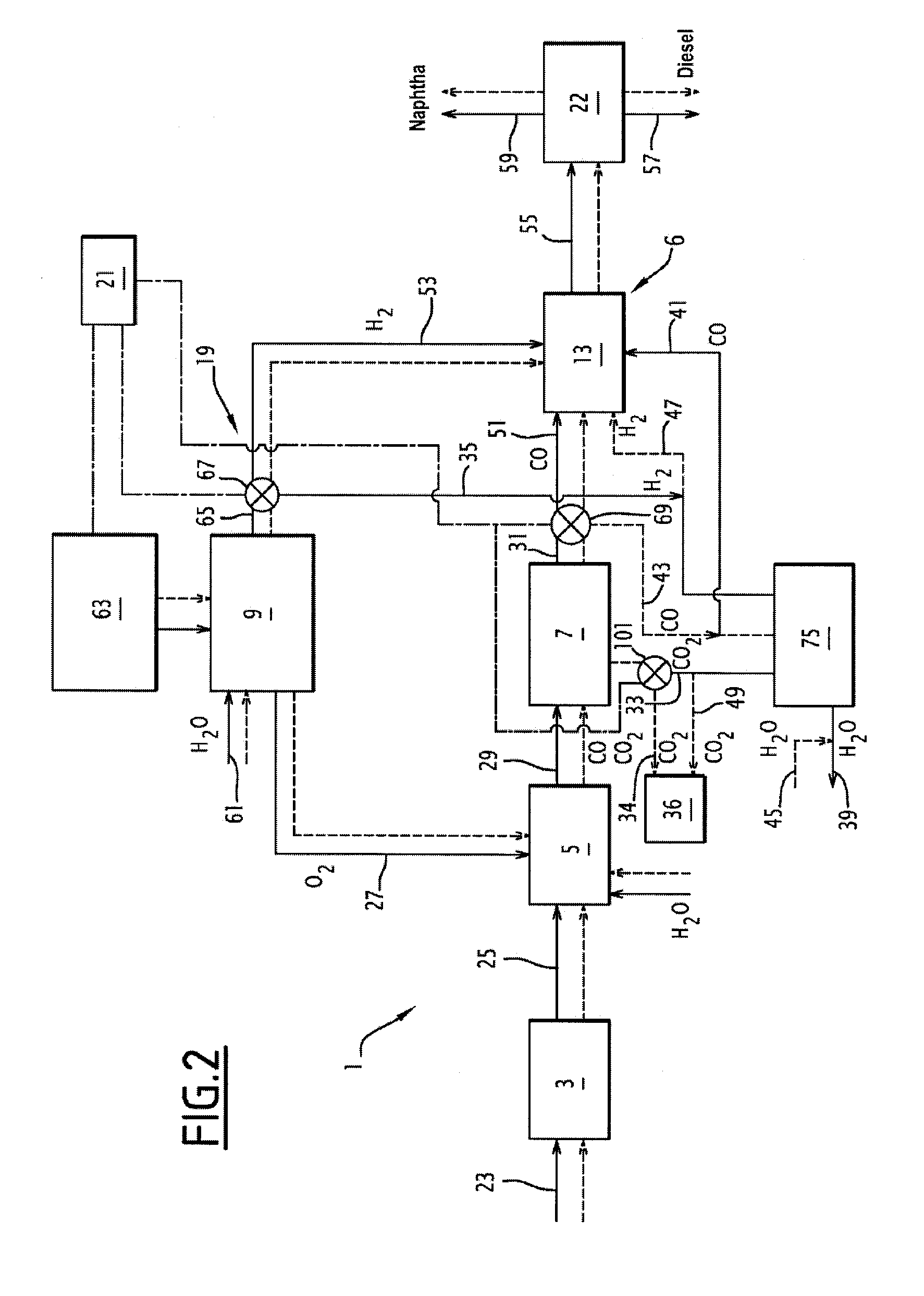
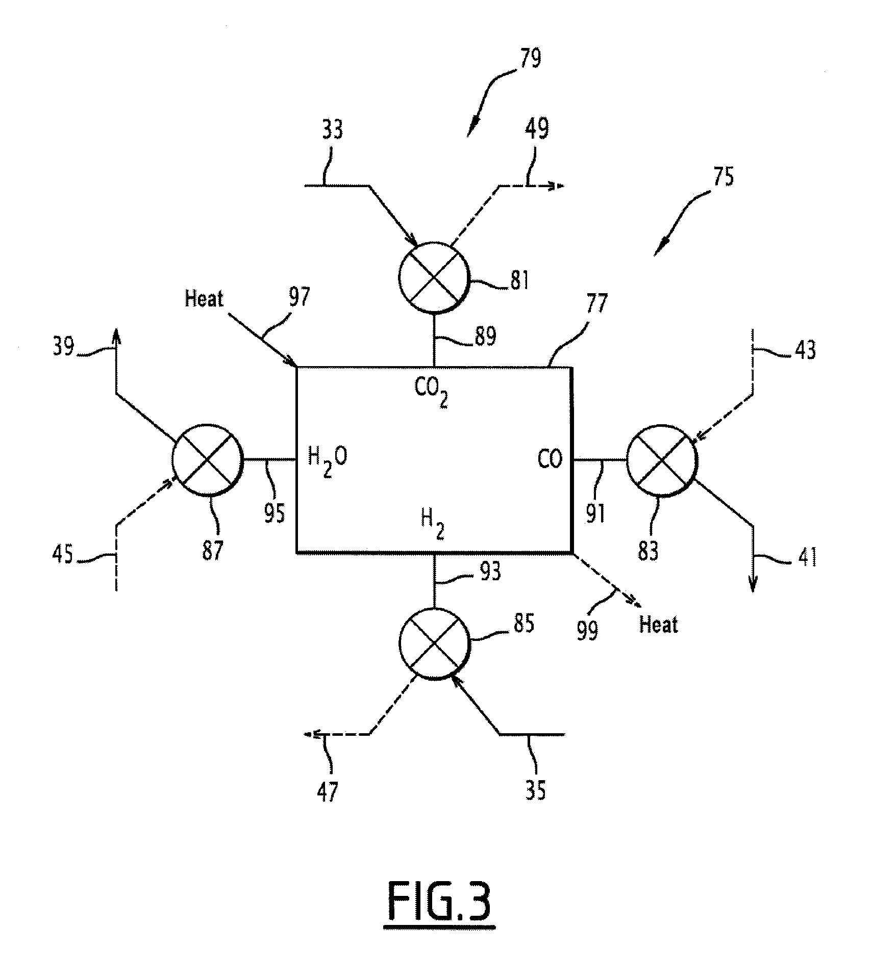
[0108]the invention will now be described with reference to FIGS. 2 and 3.

[0109]Only the points by which the second embodiment differs from the first will be detailed below. Identical elements and / or ensuring the same function in both embodiments will be designated by the same references.

[0110]As shown in FIG. 2, in the second embodiment, the first conversion unit 11 and the second conversion unit 15 are replaced with a single unit 75 which may operate reversibly. More specifically, the reversible unit 75 includes a conversion reactor 77 and a set of controlled valves 79 provided for selectively operating the conversion reactor 77 in the WGS or RWGS mode (see FIG. 3). Indeed, the reaction CO2+H2⇄CO+H2O is a reversible reaction, the equilibrium being displaced on one side or the other depending on the operating conditions in the reactor 77. Thus, the same reactor may ensure either a WGS reaction or a RWGS reaction, with the same catalyst, according to the temperature, pressure condit...

first embodiment

[0117]In the first operating mode of the facility 1, corresponding to the situation where the available electric power is relatively high, the reactor 77 operates as a RWGS unit. The three-way valve 81 has the line 33 communicate with the reactor 77 and isolates the line 49 of said reactor 77. The valve 83 has the reactor 77 communicate with line 41, and isolates the reactor from line 43. The valve 85 has the line 35 communicate with the reactor and isolates the latter from the line 47. Finally, the valve 87 has the reactor communicate with the line 39 and isolates the reactor from the line 45. Moreover, the heating circuit 97 is operating, the cooling circuit 99 being off. In this state, the reversible unit 75 ensures the same function as the first conversion unit 11 of the

[0118]In the second operating mode, corresponding to the situation where the available electric power is lower, the three-way valve 81 has the reactor 77 communicate with line 49 and isolates the latter from line...


PUM

PropertyMeasurementUnit
electric poweraaaaaaaaaa
grain sizeaaaaaaaaaa
pressureaaaaaaaaaa

Abstract

An assembly for producing at least one synthetic hydrocarbon from at least one inflowing stream of carbon monoxide and one inflowing stream of carbon dioxide is provided. The assembly includes an electrolyzer provided for producing a first stream of hydrogen, a first conversion unit provided for producing an intermediate stream of carbon monoxide from at least one portion of the inflowing stream of carbon dioxide and hydrogen, a reactor for synthesizing said synthetic hydrocarbon; a second conversion unit provided for producing a second stream of hydrogen from carbon monoxide and water, the second hydrogen stream being directed towards the synthesis reactor; a guide assembly provided for selectively distributing the inflowing stream of carbon monoxide between the second conversion unit and the synthesis reactor, and for selectively distributing the first hydrogen stream between the first conversion unit and the synthesis reactor; a control unit provided for controlling the guide assembly.

Description

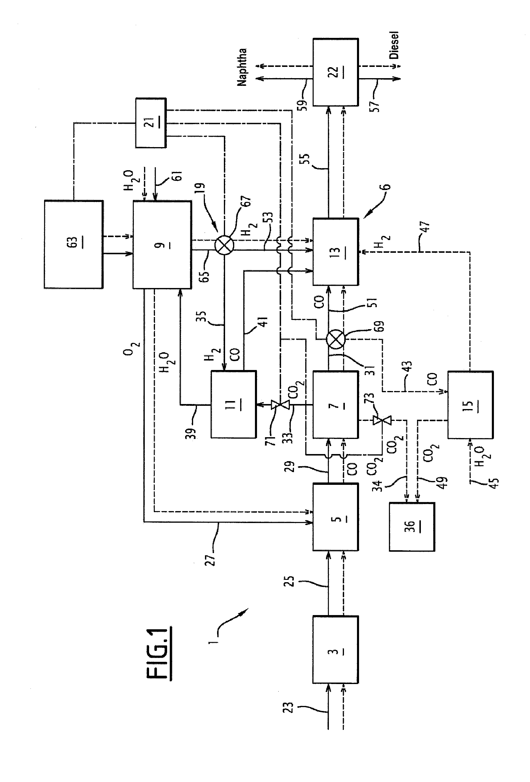
[0001]The present invention generally relates to the production of synthetic hydrocarbons from carbonaceous material.[0002]More specifically, the invention according to a first aspect relates to an assembly for producing at least one synthetic hydrocarbon from at least an inflowing stream of carbon monoxide and an inflowing stream of carbon dioxide, the assembly comprising:[0003]an electrolyzer provided for producing a first stream of hydrogen from water and from electricity,[0004]a first conversion unit provided for producing an intermediate stream of carbon monoxide from at least a portion of the inflowing stream of carbon dioxide and from hydrogen,[0005]a reactor for synthesis of said synthetic hydrocarbon from at least hydrogen, from at least a portion of the inflowing stream of carbon monoxide and from the intermediate stream of carbon monoxide.BACKGROUND[0006]Such an assembly is known from WO 2008 / 033812, which describes a production assembly comprising a gasification unit, a ...

Claims


Application Information

Patent Timeline
Patent Type & Authority Applications(United States)
IPC IPC(8): C07C27/00B01J19/00
CPCC01B3/12C10J2300/0943C01B2203/062C10G2/30C10J3/00C10J2300/1659C10J2300/1684C25B1/04Y02E60/364Y02E60/366C10K1/005C10K3/026C10K3/04C10J2300/0906C10J2300/0909C10J2300/0916C01B2203/0283Y02P20/145Y02E60/36Y02P20/00Y02P30/00Y02E60/32
Inventor LECOMPTE, MICHEL
Owner AREVA
Learn More