Application of phasor measurement units (PMU) for controlled system separation

a technology of phasor measurement unit and controlled system, which is applied in the direction of process and machine control, instruments, electric devices, etc., can solve the problems of major blackout events, indirect costs up to billions of dollars, and propagation of failures into other infrastructures such as communication, water supply, natural gas and transportation systems,

Active Publication Date: 2012-05-17
ELECTRIC POWER RES INST INC
View PDF0 Cites 51 Cited by
  • Summary
  • Abstract
  • Description
  • Claims
  • Application Information

AI Technical Summary

Problems solved by technology

Large power system blackouts, although infrequent, may influence up to tens of millions of people and result in direct costs up to billions of dollars.
There are also indirect costs such as possible social disruptions and the propagation of failures into other infrastructures such as communication, water supply, natural gas, and transportation systems.
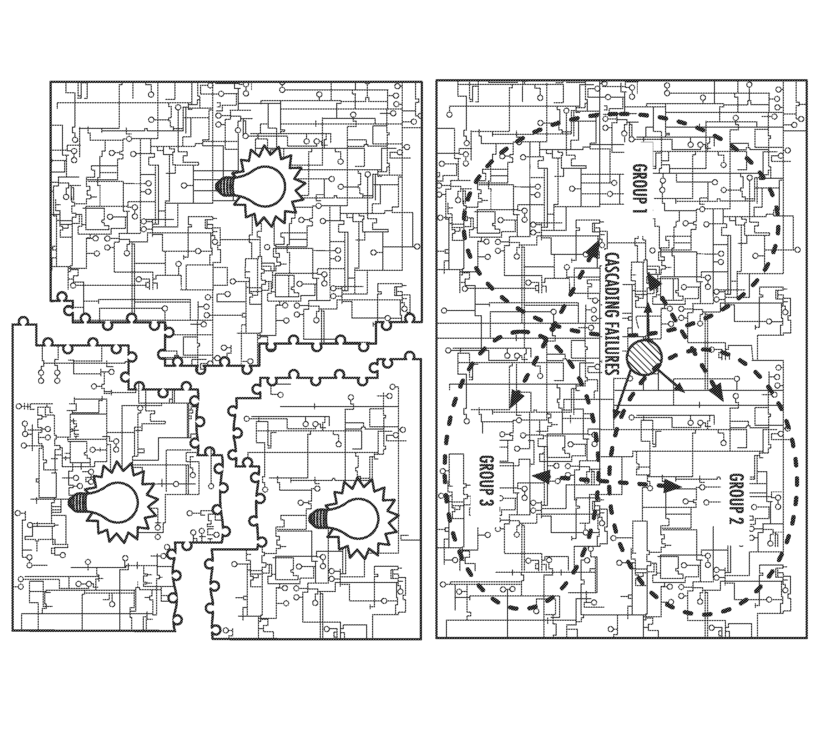
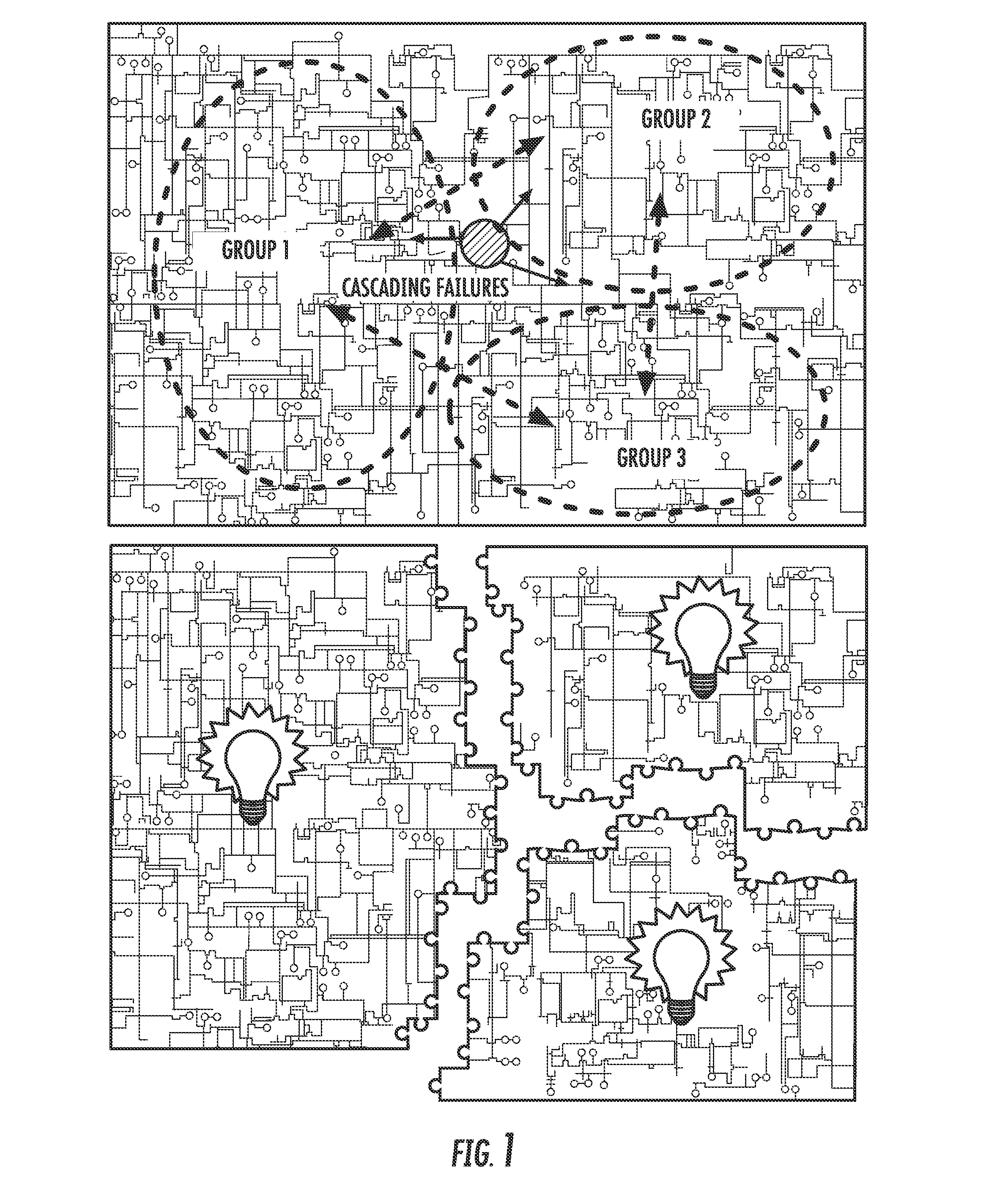
Historically, major blackout events started with cascading failures of transmission components in a power system.
Those failures were often dependent.
The first few failures were mainly caused by unanticipated disturbance events (e.g. short-circuit faults due to tree-to-line contacts and transmission outages due to severe weather conditions); thus, some transmission components became out-of-service thereafter, and as a result, overloads occurred on some other transmission components causing overload protection to trip those components and generate more overloads and failures such that the failures cascaded and spread to a wide area.
The cascading failures gradually weakened the connection of the power system and caused unintentional system separation and severe stability problems leading to a large-area blackout.
When cascading failures occur, it is difficult for system operators at control centers to take corrective actions in a matter of a few minutes or even seconds; thus, automatic protection and control schemes are required in preventing, slowing, or mitigating cascading failures.
However, protecting interconnected power systems against cascading failures and the stability problems incurred poses a challenge to power system engineers because power systems in the real world are often huge and complex while the time for online computations and decision making for control actions is quite limited.
One of the most severe stability problems that may occur with the spread of cascading failures is loss of synchronism.
When cascading failures continuously weaken the power system and impact the connections between interconnected sub-systems or control areas, inter-area oscillations will happen and grow.
If not damped, oscillations will evolve into angle separation between two or more groups of generators, namely loss of synchronism, to result in outages of generators and transmission devices.
In an unpredictable way, the system may collapse and separate into electrical islands.
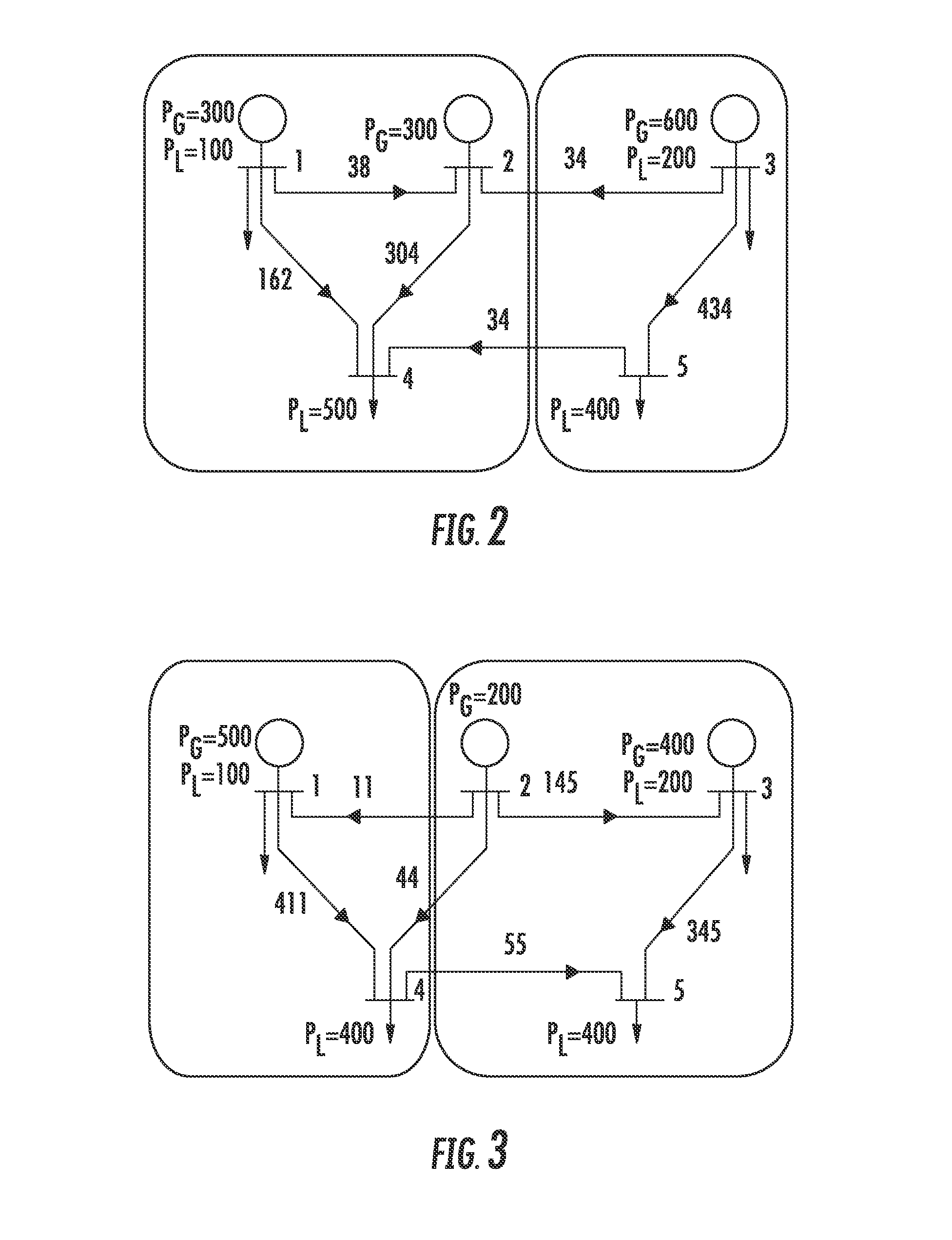
Because the formation of those islands is not in a designed manner, it is unavoidable to cause problems such as having (1) large imbalances between generation and load exist in some islands (Excessive load in a load-rich island has to be shed timely to prevent rapid frequency declines of generators while excessive generation has to be rejected in a generation-rich island.
Consequently, large-area power outages may be caused by the unplanned island formation.
); (2) some transmission lines being overloaded and then tripped—possibly resulting in more failures and further system separation within islands; and (3) the possibility of the generators that tend to lose synchronism in one island formed, making it difficult for them to cohere with each other spontaneously—which could lead to further outages of generators or transmission devices, and even worse, separation may continue in that island.
The above shows that unintentional system separation may not stop cascading failures.
In contrast, it may worsen the situation and lead to large-area blackouts.
After the separation, significant power imbalances existed in islands: the Western and South-East islands are rich in load and the North-East island is rich in generation.
The large power imbalance in the Western island induced a severe frequency drop and caused an interruption of supply for more than 15 million European households.

Method used


Image

  • Application of phasor measurement units (PMU) for controlled system separation
  • Application of phasor measurement units (PMU) for controlled system separation
  • Application of phasor measurement units (PMU) for controlled system separation

Examples


example

[0167]A 179-bus system, shown in FIG. 17, is a simplified model of a WECC AC transmission system. The system has 29 generators, 179 buses and 263 branches. The base case has a total generation of 61.4 GW and a total load of 60.8 GW.

[0168]To demonstrate the inventive controlled system separation scheme, a multi-contingency process continuously weakening the system until angle separation was used. The multi-contingency process contains 6 successive three-phase faults and line trips around the Malin interface (bus 83 in the 179-bus system), which was involved in the 1996 US Western Interconnection blackout. Table 2 gives these faults, which occur at the interval of 40 seconds and are respectively cleared after 6 cycles by tripping the fault lines. “#” indicates the locations of the three-phase faults. Note that these faults and line trips never break the connection at the Malin interface.

[0169]The locations of the six faults are also indicated by numbers in FIG. 18. The figure also hig...


PUM


Abstract

This invention relates to a PMU-based controlled system separation method to protect against a catastrophic blackout. The method includes the steps of performing an offline analysis of an electrical transmission network to partition generators into a number of coherent groups, performing online monitoring of the transmission network to determine a separation interface and frequencies and damping ratios of dominant inter-area modes, and estimating the risk of system separation to perform real-time control.

Description

BACKGROUND OF THE INVENTION[0001]The present invention relates generally to electrical transmission system protection, and more particularly to a PMU-based controlled system separation method to protect against a catastrophic blackout.[0002]A major goal in transmission system protection is to avoid cascading failures. Large power system blackouts, although infrequent, may influence up to tens of millions of people and result in direct costs up to billions of dollars. There are also indirect costs such as possible social disruptions and the propagation of failures into other infrastructures such as communication, water supply, natural gas, and transportation systems. The vital importance of electric power to our society motivates continued attention to maintaining power system stability and developing effective self-healing protection and control strategies to prevent blackouts under major disturbances (either nature or man-made).[0003]Historically, major blackout events started with...

Claims


Application Information

Patent Timeline
Patent Type & Authority Applications(United States)
IPC IPC(8): G06F1/28G06F19/00G01R21/00
CPCY04S10/265Y02E60/728H02J3/14H02J3/24H02J13/0006H02J2003/007Y02E60/74Y02B70/3225Y04S20/222Y04S40/22Y02E60/76Y04S10/30H02J2003/388H02J3/388H02J2203/20H02J13/00002Y02E60/00Y04S10/00Y04S40/20Y04S10/22Y02E40/70H02J2310/60H02J3/144H02J3/0012
Inventor SUN, KAIHUR, KYEONZHANG, PEI
Owner ELECTRIC POWER RES INST INC
Why Eureka
Try Eureka