Yaw-rate sensor and method for operating a yaw-rate sensor

a sensor and yaw-rate technology, applied in the direction of acceleration measurement using interia forces, turn-sensitive devices, instruments, etc., can solve the problems of error signals during operation, inability to distinguish between coriolis force and force, and limitation is extremely disadvantageous, so as to achieve higher deflection

Active Publication Date: 2012-05-24
ROBERT BOSCH GMBH
View PDF22 Cites 53 Cited by
  • Summary
  • Abstract
  • Description
  • Claims
  • Application Information

AI Technical Summary

Benefits of technology

[0006]The yaw-rate sensor according to the present invention and the method according to the present invention have the advantage over the related art that they do not have the disadvantages of the related art and are insensitive to interfering, in particular angular accelerations. Furthermore, it is advantageously possible that, due to a differential evaluation, interfering linear accelerations and angular accelerations induce no, or at least only relatively weak, interference signals. These advantages are achieved according to the present invention by a yaw-rate sensor which has a substrate having a main plane of extension for detecting a yaw rate about a first axis extending parallel to the main plane of extension, the yaw-rate sensor having a first Coriolis element, a second Coriolis element, a third Coriolis element, and a fourth Coriolis element, the first Coriolis element and the fourth Coriolis element being drivable in the same direction parallel to a second axis extending parallel to the main plane of extension and perpendicularly to the first axis, the first Coriolis element and the second Coriolis element being drivable in opposite directions parallel to the second axis, and the first Coriolis element and the third Coriolis element being drivable in opposite directions parallel to the second axis.
[0007]According to one preferred refinement it is provided that the Coriolis elements are connected to each other via coupling elements, the coupling elements being preferably connected to the substrate. This makes it advantageously possible that the parallel interference modes with respect to the detection are shifted to high frequencies compared to the detection modes in opposite directions.
[0008]According to another preferred refinement it is provided that the coupling element has an axis of rotation parallel to the main plane of extension, the axis of rotation preferably running parallel to the first axis or to the second axis. This makes it advantageously possible that the parallel interference modes with respect to the detection are shifted to high frequencies compared to the detection modes in opposite directions.

Problems solved by technology

The occurrence of these forces disadvantageously results in error signals during operation.
Using conventional sensors, it is impossible to differentiate between Coriolis force and the force which arises due to the angular acceleration about the x axis.
This limitation is extremely disadvantageous, since angular accelerations occur as interference variables.

Method used


Image

  • Yaw-rate sensor and method for operating a yaw-rate sensor
  • Yaw-rate sensor and method for operating a yaw-rate sensor
  • Yaw-rate sensor and method for operating a yaw-rate sensor

Examples


Embodiment Construction

[0023]In the figures, identical parts are provided with identical reference numerals and are therefore normally named or mentioned only once.

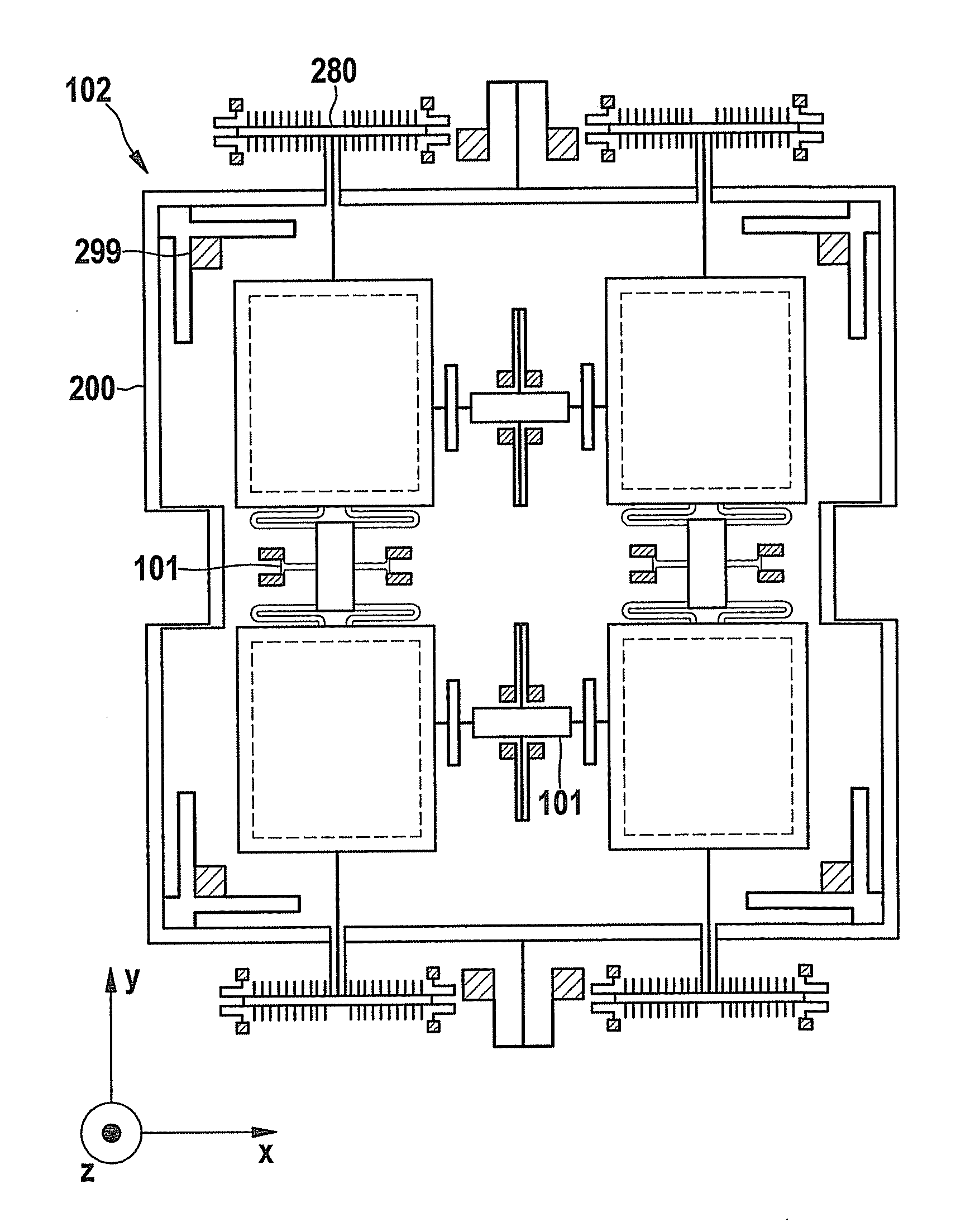
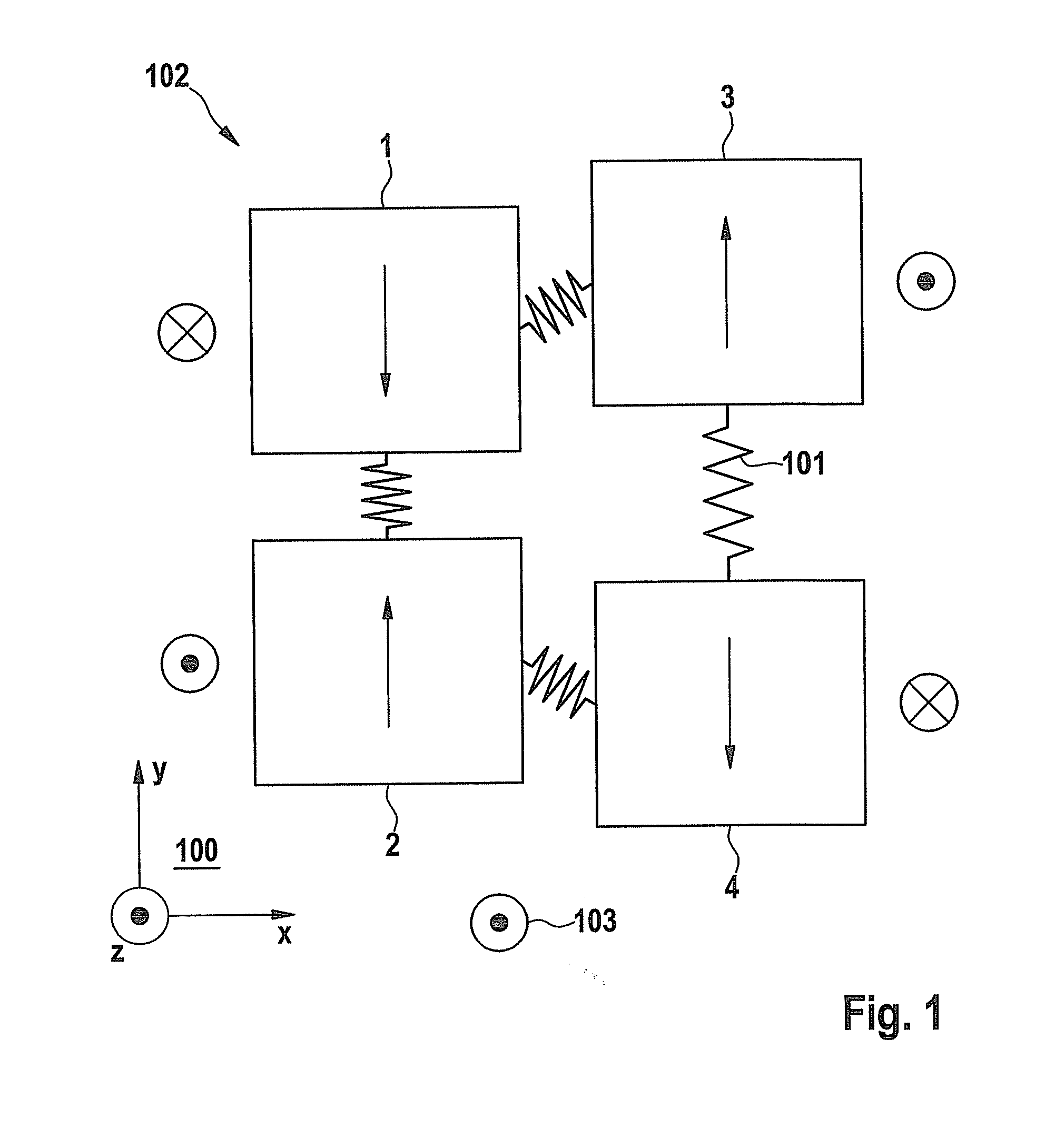
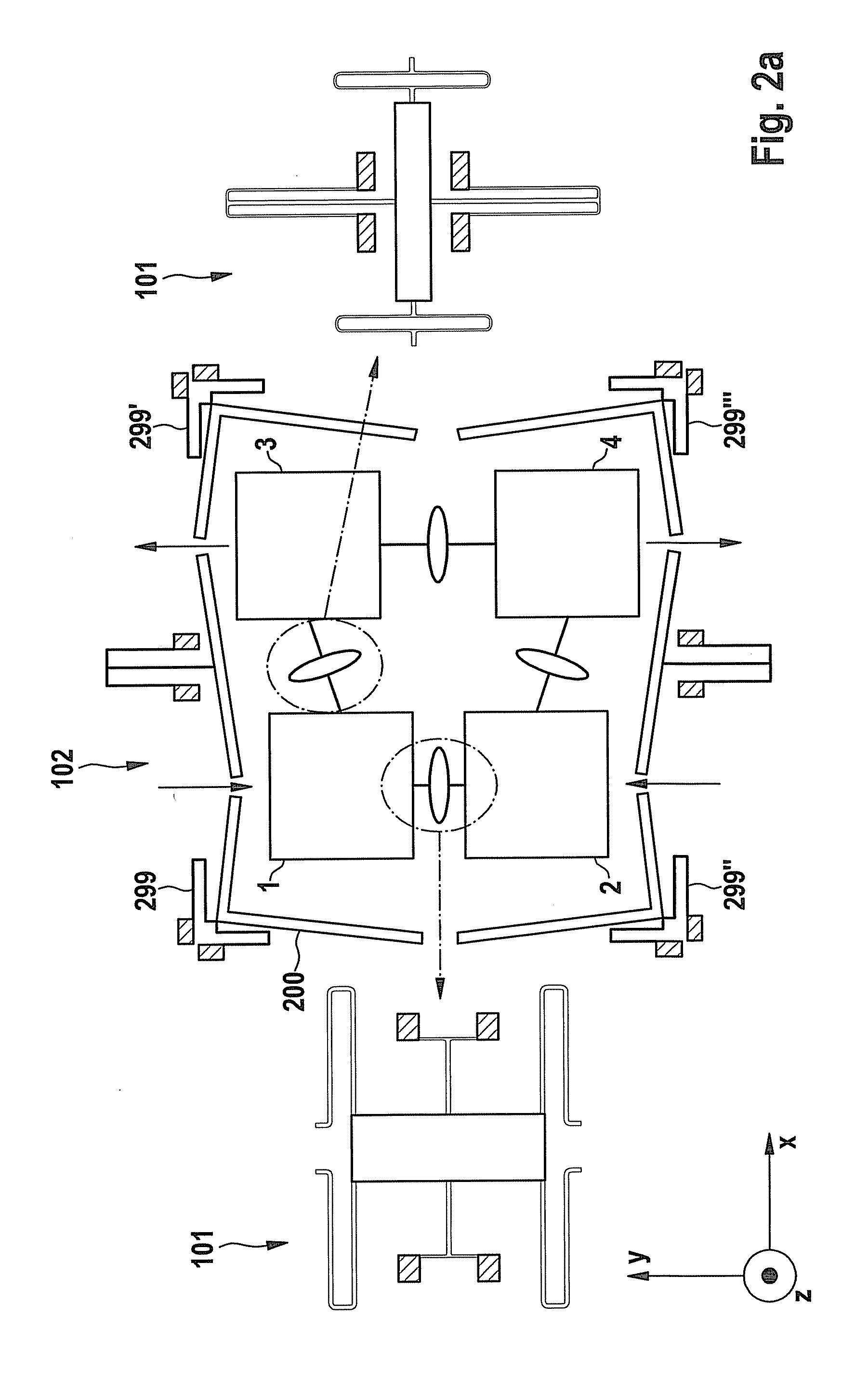
[0024]FIG. 1 shows a schematic illustration of an exemplary specific embodiment of yaw-rate sensor 102 according to the present invention. Yaw-rate sensor 102 has four Coriolis elements 1, 2, 3, 4, which are designed as linearly oscillating masses (also referred to hereinafter as partial oscillators or partial structures). A substrate (not illustrated) has a main plane of extension 100. Second axis (drive axis) Y is in main plane of extension 100. Drive means (not illustrated), which are preferably designed as comb structures, are provided for capacitively inducing oscillation of the Coriolis elements parallel to the second axis. Coriolis elements 1, 2, 3, 4 are connected to each other via coupling elements 101, which are preferably designed as rockers. The movements of the partial oscillators in the operation mode are indicated by the arrows. ...


PUM


Abstract

A yaw-rate sensor includes: a substrate having a main extension plane for detecting a yaw rate about a first axis extending parallel to the main extension plane; a first Coriolis element; a second Coriolis element; a third Coriolis element; and a fourth Coriolis element. The first Coriolis element and the fourth Coriolis element are drivable in the same direction parallel to a second axis extending parallel to the main extension plane and perpendicularly to the first axis. The first Coriolis element and the second Coriolis element are drivable in opposite directions parallel to the second axis. The first Coriolis element and the third Coriolis element are drivable in opposite directions parallel to the second axis.

Description

BACKGROUND OF THE INVENTION[0001]1. Field of the Invention[0002]The present invention relates to a yaw-rate sensor and a method for operating a yaw-rate sensor.[0003]2. Description of the Related Art[0004]Yaw-rate sensors are known from the related art. For example, a yaw-rate sensor having two oscillating mass elements is known from the published international patent application document WO 03064975 A1. Micromechanical yaw-rate sensors for yaw rates about an axis which is parallel to the sensor plane (Z′ and yaw rate Qy) are normally designed as planarly oscillating masses or as masses rotating in the plane, which are subjected to a Coriolis force, which is perpendicular to the plane, when rotation occurs. This force is ascertained either via the electrostatic counterforce needed for position feedback regulation (closed-loop regulation) or, measured, for example, via the change in capacity due to the change in the distance to the substrate (open-loop operation). In addition to the ...

Claims


Application Information

Patent Timeline
Patent Type & Authority Applications(United States)
IPC IPC(8): G01C19/56
CPCG01C19/5747
Inventor SCHEBEN, ROLFKUHLMANN, BURKHARDBALSLINK, THORSTENMEISEL, DANIEL CHRISTOPHSCHMIDT, BENJAMIN
Owner ROBERT BOSCH GMBH
Why Eureka
Try Eureka