Plarization idependent non-blocking all-optical switching device

A polarization-independent, polarized beam technology, applied in nonlinear optics, optics, polarizing elements, etc., can solve the problems of maintaining the polarization state, not being able to maintain the polarization state of light, and cumulative loss

Inactive Publication Date: 2004-06-30
REVEO
View PDF12 Cites 0 Cited by
  • Summary
  • Abstract
  • Description
  • Claims
  • Application Information

AI Technical Summary

Problems solved by technology

Since conventional optical fibers cannot maintain the polarization state of light, a polarizer is required during or before each exchange, resulting in a rapid cumulative loss
Although there have been some advances in polarization maintaining fiber technology (see U.S. Patent 4,904,052), these fibers generally cannot maintain the polarization state while maintaining the purity required for polarization exchange
Moreover, polarization maintaining fiber is usually much more expensive than ordinary fiber
One solution is to use an optical amplifier before or after each switching device, although this means bulky equipment and greatly increased costs

Method used


Image

  • Plarization idependent non-blocking all-optical switching device
  • Plarization idependent non-blocking all-optical switching device
  • Plarization idependent non-blocking all-optical switching device

Examples


Embodiment Construction

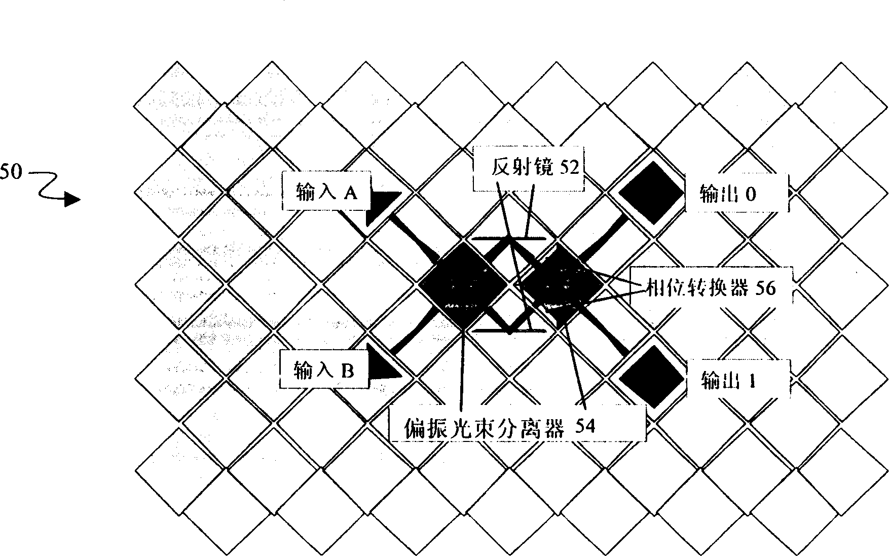
[0023] Figure 3-4 B shows a device designed according to the idea of ​​the present invention. The invention may be described by way of example of a 2x2 all-optical, polarization independent switch 50 in its simplest form. The unpolarized incident light from the input fibers A and B is split into two polarized beams with orthogonal polarization directions at the first element. Unlike a typical polarization switch, the two beams are routed separately through different paths of the same switching device, preferably with the same optical path length in the same switch. These beams are then combined at an element near the output fibers 0,1. As shown, this embodiment includes a plurality of polarizing beam splitters 54, a plurality of phase shifters 56, and a plurality of mirrors 52 configured so that two discrete inputs A and B can be coupled to two discrete Any combination of 0 and 1 output. These elements can also be scaled up to facilitate switching with a large number of i...


PUM


Abstract

The present invention includes a polarization independent optical interconnect device for selsctively interconnecting a plurality of optical signals between a plurality of outputs. The present invention may provide advantages typically associated with conventional polarization based switches, including terabit per second data rates and high speed switching, to facilitate use in fiber optic networks. Moreover, the switch of this invention is polarization independent, and therefore, may route either polarized or unpolirized light. Since both the input and output light may be unpolarized, the switch of this invention may have a high light efficiency (i.e. no losses associated with an input polirizer) and minimal insertion losses as compared to typical polarization based switches.

Description

technical field [0001] The present invention relates to switching equipment and, in particular, to optical switching equipment for routing optical signals between multiple inputs and multiple outputs. Background technique [0002] The use of optical fibers, especially for telecommunication transmission media, has many advantages over current telecommunication media such as copper cables. For example, optical fibers can support signals with wider bandwidths, allowing larger amounts of information to be transmitted in a given amount of time. Furthermore, optical fiber emits little or no electromagnetic or radio frequency radiation, so the impact on the environment is negligible. Conversely, optical fibers are relatively insensitive to electromagnetic and radio frequency radiation from the surrounding environment. Therefore, with the development of such fields as supercomputing, telecommunications and military C 3 I applications depend on the ability to route data at ever in...

Claims


Application Information

Patent Timeline
Patent Type & Authority Applications(China)
IPC IPC(8): G02B5/30G02F1/13G02F1/31H04Q11/00
CPCH04Q2011/0026H04Q2011/0035H04Q11/0005H04Q2011/0024
Inventor 何战格雷戈里·J·哈姆林塞尔西奥·梅尔特庆萨迪克·M·法里斯
Owner REVEO
Why Eureka
Try Eureka