barge pusher

a pusher and barge technology, applied in the direction of motor-driven power plants, special-purpose vessels, vessel construction, etc., can solve the problems of limited positioning of the propeller components on the barge, and it is difficult to transport both the power component and the propeller component together

Inactive Publication Date: 2012-05-24
POSEIDON BARGE LTD +1
View PDF11 Cites 6 Cited by
  • Summary
  • Abstract
  • Description
  • Claims
  • Application Information

AI Technical Summary

Benefits of technology

[0006]The present disclosure provides a hydraulic thruster apparatus for maneuvering a marine vessel. In one aspect of the present disclosure, the hydraulic thruster apparatus comprises a hydraulic power unit positionable on a deck of the marine vessel and a thruster unit connectable to the marine vessel. The hydraulic power unit includes an engine and a hydraulic pump connected to the engine. The thruster unit includes a frame removably connectable to the marine vessel and a propeller assembly connected to the frame. The propeller assembly includes a hydraulic motor and a propeller drivingly connected to the hydraulic motor. The propeller provides a thrust force that acts to move the marine vessel. The thruster unit further comprises a rotating mechanism for rotating the propeller assembly about a generally vertical axis relative to the frame and a raising and lowering

Problems solved by technology

The problem with these existing designs is that the locations on the barge where the propeller component can be positioned are limited

Method used


Image

  •  barge pusher
  •  barge pusher
  •  barge pusher

Examples


Embodiment Construction

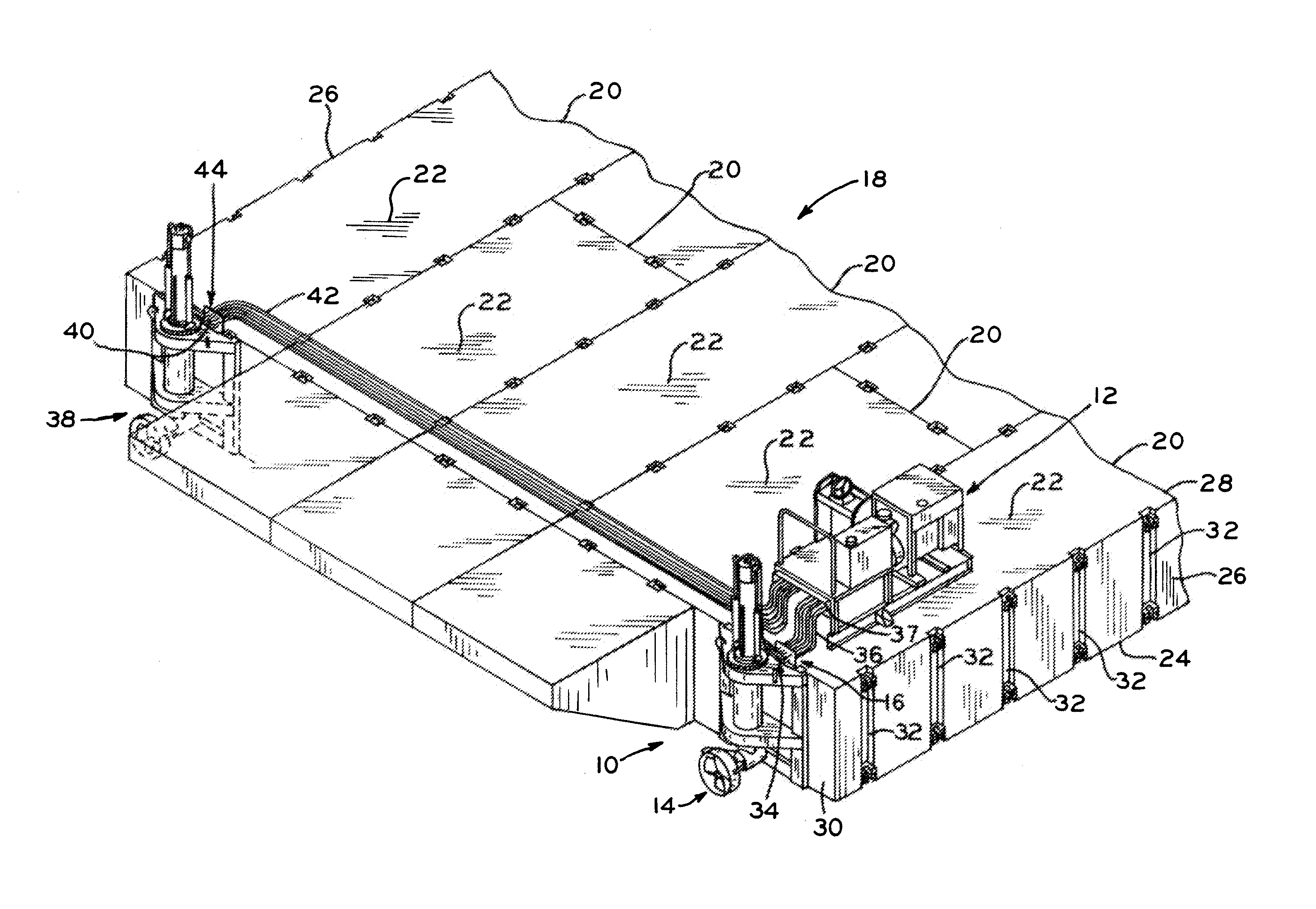
[0031]The present disclosure provides a barge construction pusher unit that is readily mountable to and removable from an individual barge. Such a barge pusher unit is used to maneuver a barge on a waterway into a desired position at a construction site. The barge pusher unit can be used with a single barge as illustrated in FIG. 4, for example, or two or more barges connected together as illustrated in FIG. 1.

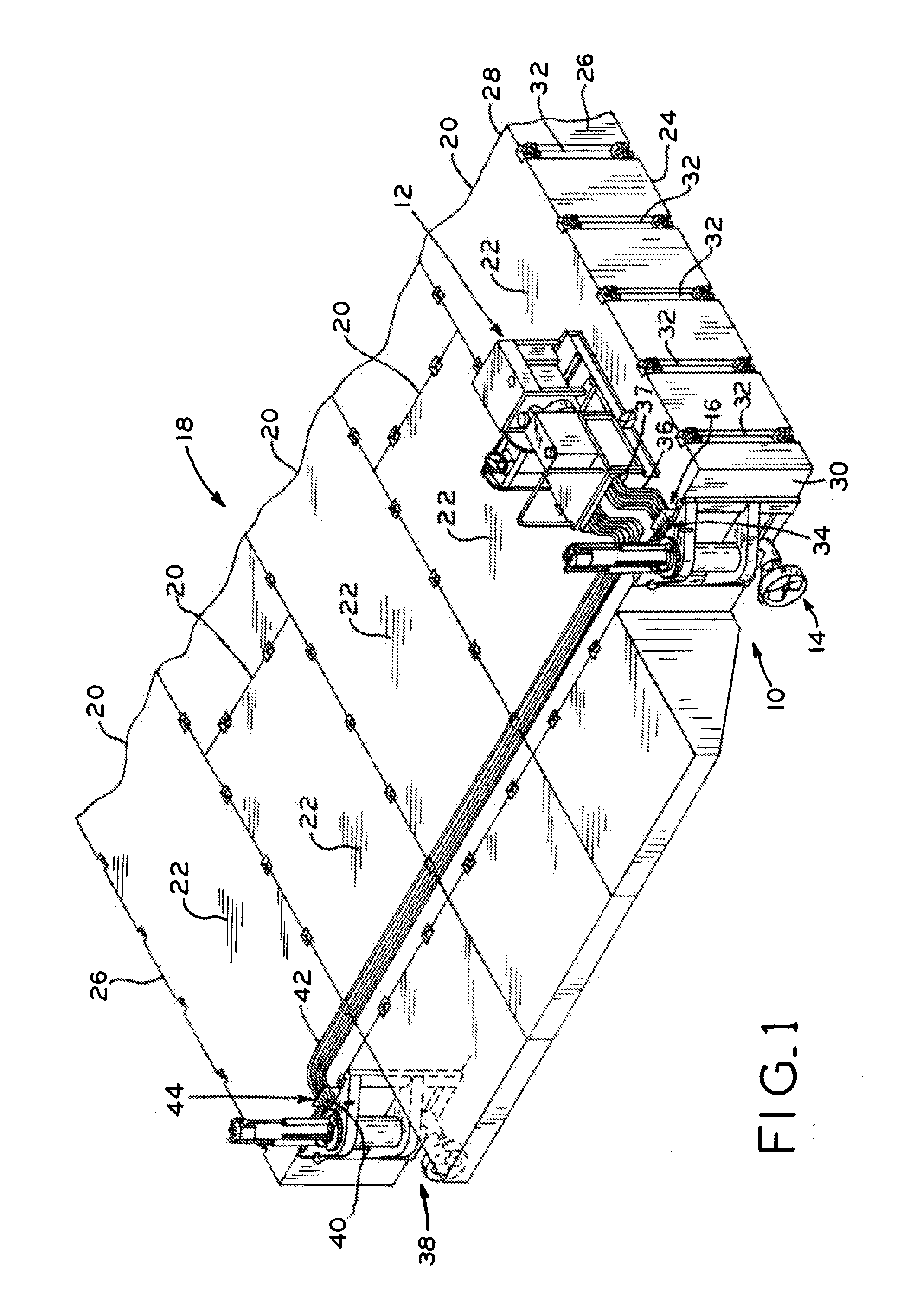
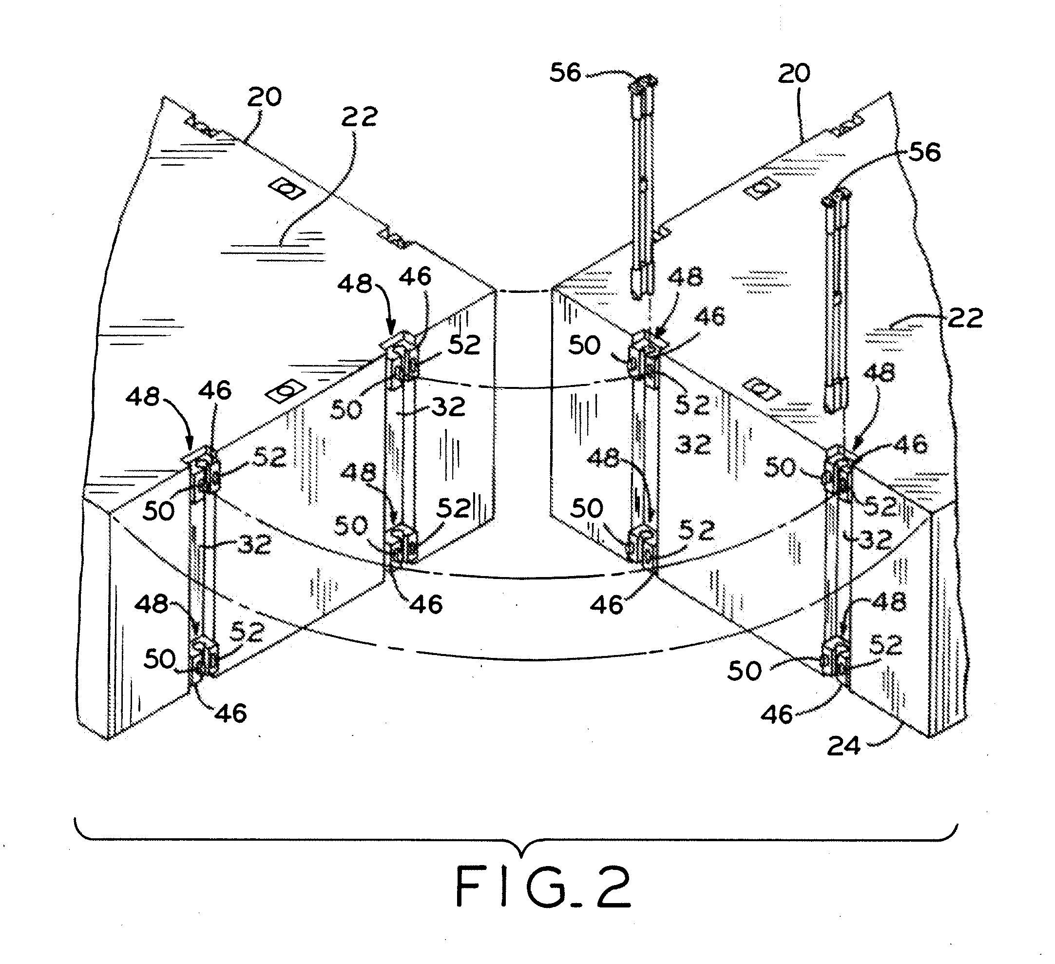
[0032]FIG. 1 illustrates barge pusher unit 10 according to an exemplary embodiment of the present disclosure. In the exemplary embodiment of FIG. 1, barge pusher unit 10 includes hydraulic power unit 12, thruster unit 14, and thruster unit connection panel 16. Barge assembly 18 is illustrated in FIG. 1 comprising a plurality of barges 20 interconnected together, as discussed in more detail below. Each barge 20 generally includes deck 22, bottom 24 opposite deck 22, side walls 26, front wall 28, and rear wall 30 opposite front wall 28. Side walls 26, front wall 28, and rear wal...


PUM


Abstract

A sectional barge assembly and a hydraulic thruster apparatus for maneuvering the sectional barge assembly. The hydraulic thruster apparatus includes a hydraulic power unit and a thruster unit. The hydraulic power unit includes an engine and a hydraulic pump connected to the engine. The thruster unit includes a hydraulic motor and a propeller drivingly connected to the hydraulic motor to provide a thrust force that acts to move the sectional barge assembly. The sectional barge assembly includes a plurality of barges interconnected by connector devices that are also used to interconnect the thruster unit to the sectional barge assembly. Further, a hydraulic connection panel is mounted on the thruster unit and includes a plurality of hydraulic connectors which allow a plurality of hydraulic lines to be removably connectable thereto, respectively. By this arrangement, the hydraulic pump provides pressurized hydraulic fluid through the hydraulic lines thereto the hydraulic motor and other components of the thruster unit. Additionally, the thruster unit includes at least one hydraulic cylinder for controlling vertical rectilinear sliding of a thruster unit mast between a top position and a bottom position. The thruster unit also includes a rotating mechanism for rotating the mast and a propeller assembly of the thruster unit about a longitudinal axis of the mast.

Description

BACKGROUND[0001]1. Technical Field[0002]The present disclosure relates to a barge propulsion system.[0003]2. Description of the Related Art[0004]Barges are commonly used on waterways during large construction projects to support heavy equipment. In order to maneuver the barge and the heavy equipment into a desired position, hydraulic thruster units are used. Hydraulic thrusters may be formed as self-contained units that are readily mountable to and removable from individual barges.[0005]Existing hydraulic thruster units contain a single unit having a power component and a propeller component that are not easily disconnected from each other. The problem with these existing designs is that the locations on the barge where the propeller component can be positioned are limited. Further, it is difficult to transport both the power component and the propeller component together to a desired construction project.SUMMARY[0006]The present disclosure provides a hydraulic thruster apparatus fo...

Claims


Application Information

Patent Timeline
IPC IPC(8): B63B21/56B63H21/165
CPCB63B35/38B63H20/08B63H20/106B63H2021/307B63H20/14B63H21/30B63H23/26B63H20/12
Inventor EMCH, JEFFREY J.
Owner POSEIDON BARGE LTD
Why Eureka
Try Eureka