Anesthetic breathing apparatus having volume reflector unit with controllable penetration

a technology volume reflector, which is applied in the field can solve the problems of gas leakage, reduced patient safety, and inability to achieve the clinical effects of anesthetic agents, and achieves the effects of improving the ventilatory performance of anesthetic breathing apparatus, reducing patient safety, and increasing patient safety

Active Publication Date: 2012-05-24
MAQUET CRITICAL CARE
View PDF2 Cites 0 Cited by
  • Summary
  • Abstract
  • Description
  • Claims
  • Application Information

AI Technical Summary

Benefits of technology

[0029]Some embodiments of the invention provide for increased safety of the anesthetic breathing apparatus while not increasing cost.
[0032]Some embodiments of the invention provide for anesthetic breathing apparatus having a volume reflector and a compact design.
[0033]Some embodiments of the invention also provide for increased patient safety as delivery of sufficient oxygen is provided to the patient and hypoxia is effectively avoided.
[0034]Some embodiments of the invention also provide for improved ventilatory performance of an anesthetic breathing apparatus as a compressible volume and flow resistance is kept low in a volume reflector provided.

Problems solved by technology

Furthermore, gas leakage may occur, e.g. leakage at a tracheal tube, or other locations in the anesthetic breathing apparatus.
This crossing of the reflector driving gas over the volume reflector is called break-through or penetration of driving gas through the reflector unit and is an undesired condition, as the patient may receive less anesthetic agent than needed.
This reduces patient safety as desired clinical effects to be obtained by the anesthetic agent may not be achieved.
This compensation is made to ensure the intended delivery of anesthetic gas, as even a small amount of mixing of the driving gas into the breathing circuit is regarded as undesired.
Awakening or awareness of the patient may occur during anesthesia, which is highly undesired.
There is also a need to reduce the reflector volume, e.g. due to limited space when wanting to integrate the reflector volume in an anesthesia machine.
A compressible reflector volume of 2-3 liters constitutes a large compressible volume that causes delays and is a source of inaccurate ventilatory regulation.
With regard to such comparatively low tidal volumes, a compressible volume of 2-3 liters is disadvantageous for ventilatory regulation.
Moreover, a well defined front of the gas pillars requires a narrow tube or channel for the reflector volume, which consequently increases gas flow resistance, which is undesired.
Increased resistance results e.g. in increased work of breathing of the patient during expiration, or leads to incomplete discharging of the patient's lungs during expiration.
However, reducing the reflector volume to a volume corresponding to a tidal volume, or less, raises other issues, as it would e.g. amplify the losses of anesthetic gas.
The reflector volume is simply not sufficient for the task.

Method used


Image

  • Anesthetic breathing apparatus having volume reflector unit with controllable penetration
  • Anesthetic breathing apparatus having volume reflector unit with controllable penetration
  • Anesthetic breathing apparatus having volume reflector unit with controllable penetration

Examples


Embodiment Construction

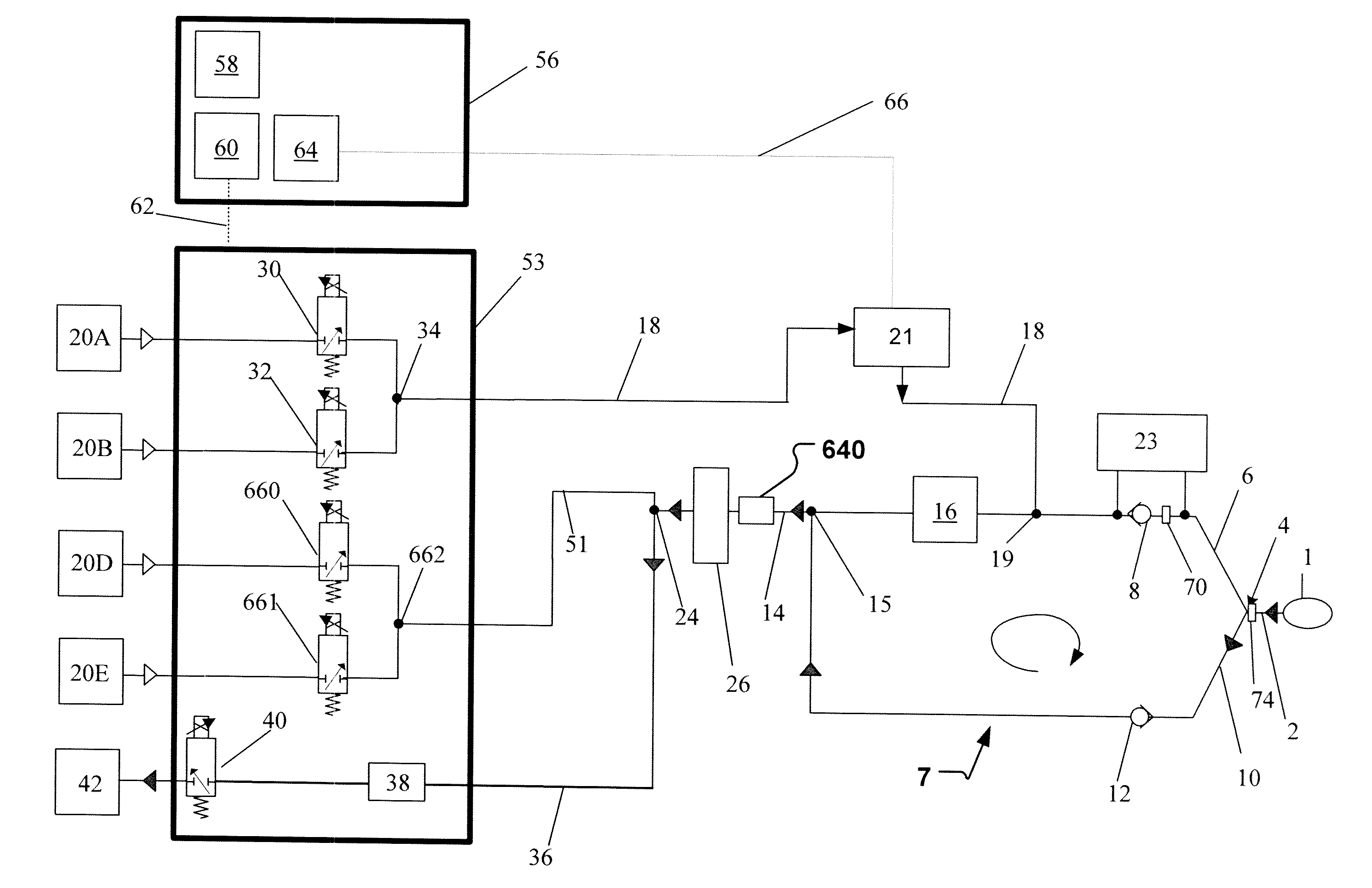
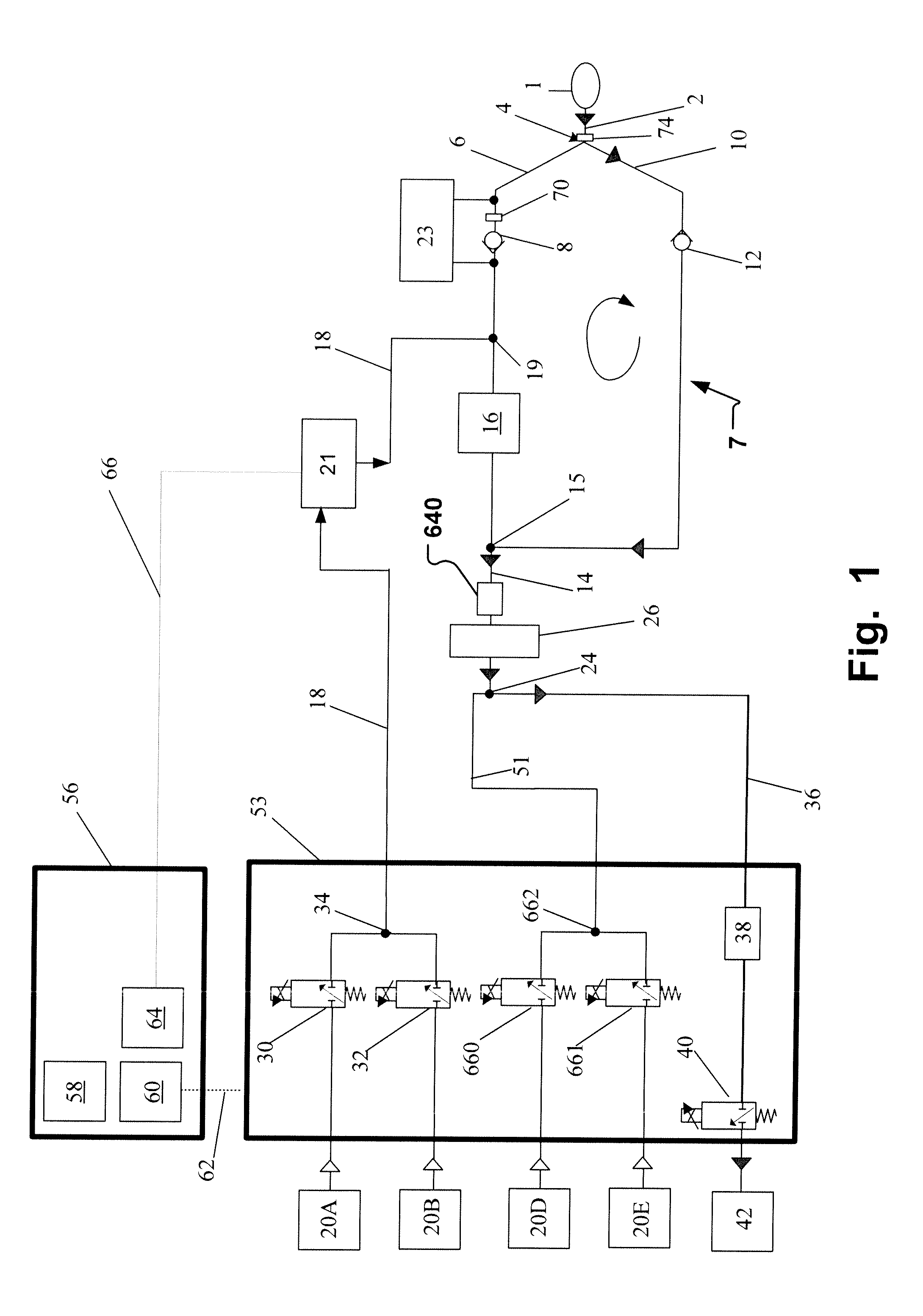
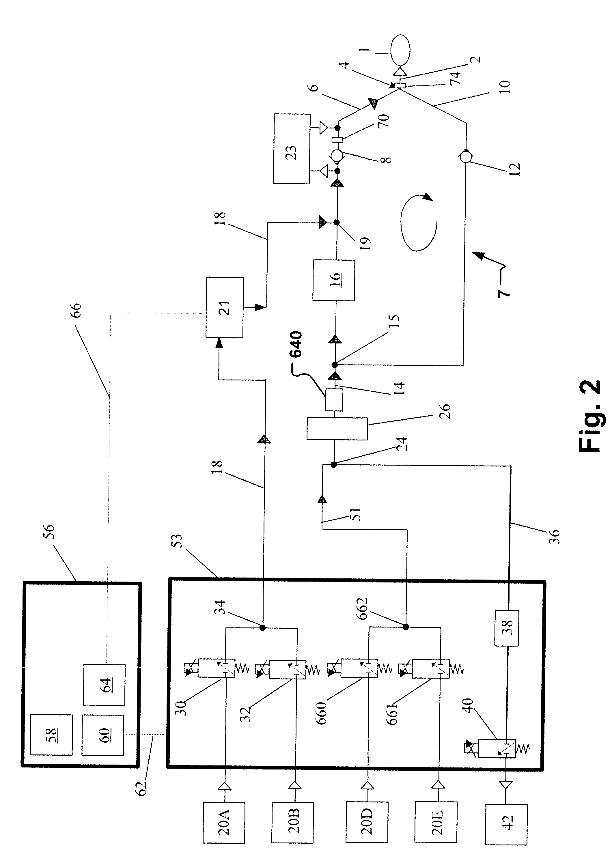
[0042]Specific embodiments of the invention will now be described with reference to the accompanying drawings. This invention may, however, be embodied in many different forms and should not be construed as limited to the embodiments set forth herein; rather, these embodiments are provided so that this disclosure will be thorough and complete, and will fully convey the scope of the invention to those skilled in the art. The terminology used in the detailed description of the embodiments illustrated in the accompanying drawings is not intended to be limiting of the invention. In the drawings, like numbers refer to like elements.

[0043]The following description focuses on an embodiment of the present invention applicable to a specific anesthetic breathing apparatus and arrangement of delivering reflector driving gas. However, it will be appreciated that the invention is not limited to this application but may be applied to many other anesthetic breathing apparatuses including for examp...


PUM


Abstract

An anesthetic breathing apparatus and system, having a patient circle system for re-breathing exhaled gases by a patient volume reflector, a fresh gas delivery line, and a gas sensor unit arranged to measure a gas stream upstream a fresh gas connection and downstream said reflector unit. The gas sensor unit provides a signal for detection of a reflector driving gas (RDG) crossing over the volume reflector during inspiration based on at least one property of the gas stream measured by the gas sensor unit. Appropriate action may be taken based on this measurement, for instance in disclosed methods.

Description

BACKGROUND OF THE INVENTION[0001]1. Field of the Invention[0002]This invention pertains in general to the field of anesthetic breathing apparatuses having a volume reflector unit for providing gas from a reflector volume thereof re-entering into a breathing circuit during inspiration.[0003]2. Description of the Prior Art[0004]In inhalational anesthesia, anesthetic reflectors for the reflection of unused, gas born, anesthetic agents in expiration gas back towards a patient.[0005]For instance in U.S. Pat. No. 4,989,597, an exchanger for open separation is disclosed. The exchanger directly interfaces a ventilator to a patient breathing circuit, and comprises a long, convoluted tube having a narrow diameter, yet large total volume. The open separation of the gases is resulting from the long mixing tube, which contains a volume of two to three liters of gas. There is no divider, such as a filter or membrane, such as in a traditional bag in bottle system, between the separated gas columns...

Claims


Application Information

Patent Timeline
Patent Type & Authority Applications(United States)
IPC IPC(8): A61M16/12A61M16/22
CPCA61M16/01A61M16/22A61M16/0093A61M2016/1025A61M16/0051A61M16/009A61M16/024A61M16/0891A61M16/104A61M16/18A61M2016/0027A61M2016/003A61M2016/102A61M2202/0208A61M2202/0241A61M2205/15A61M2205/18A61M2205/3334A61M2205/50A61M2205/502A61M2202/0007A61M16/0003A61M16/0045A61M16/10A61M2016/1035
Inventor WALLEN, LARS
Owner MAQUET CRITICAL CARE
Why Eureka
Try Eureka