Heat radiating fin

a heat radiating fin and heat sink technology, applied in semiconductor devices, lighting and heating apparatus, semiconductor devices, etc., can solve the problems of increasing the overall cost of unable to fit and tightly engage, and the heat radiating fin b>1/b takes a lot of time and labor, so as to reduce labor and time, reduce material, and fast manufacture

Inactive Publication Date: 2012-05-24
ASIA VITAL COMPONENTS SHENZHEN CO LTD
View PDF2 Cites 0 Cited by
  • Summary
  • Abstract
  • Description
  • Claims
  • Application Information

AI Technical Summary

Benefits of technology

[0007]A primary object of the present invention is to provide a heat radiating fin that enables easy assembling of it to other ones to form a heat sink and may be dismounted from and remounted to the heat sink without deformation.
[0008]Another object of the present invention is to provide a heat radiating fin that can be fabricated with largely reduced material without producing a large quantity of scraps.
[0009]A further object of the present invention is to provide a heat radiating fin that can be quickly fabricated at decreased labor and time to lower the overall cost thereof.
[0010]To achieve the above and other objects, the heat radiating fin according to the present invention includes a flat body having a front side and a rear side, a plurality of protruded portions formed on the front side of the flat body by way of stretching or drawing to have a predetermined height, and a plurality of recessed portions correspondingly formed on the rear side of the flat body behind the protruded portions. The protruded portions on the flat body of a first heat radiating fin are partially extendable into corresponding recessed portions on the flat body of a second heat radiating fin located before the first one, allowing the first and the second heat radiating fin to be easily and stably stacked.

Problems solved by technology

Therefore, the forming of the conventional heat radiating fin 1 involves in many complicated machining procedures, and the forming of the heat sink by assembling the heat radiating fins 1 takes a lot of time and labor.
Moreover, the forming of the receiving slots 111 and the retaining catches 112 by stamping produces a large quantity of scraps and is subject to high bad yield to further increase the overall cost of the heat radiating fin 1.
Therefore, when the heat radiating fin 1 dismounted from the assembled heat sink is remounted to the heat sink, it would usually fail to fitly and tightly engage with other heat radiating fins 1 as before, and tends to separate therefrom.
In brief, the conventional heat radiating fin 1 has the following disadvantages: (1) it requires extra time and labor to fabricate; (2) many complicated fabricating procedures are involved to increase the manufacturing cost; (3) a large quantity of scraps is produced; and (4) the receiving slots and the retaining catches are easily deformed under external force, preventing the dismounted heat radiating fin from being fitly and tightly remounted to the heat sink.

Method used


Image

  • Heat radiating fin
  • Heat radiating fin
  • Heat radiating fin

Examples


first embodiment

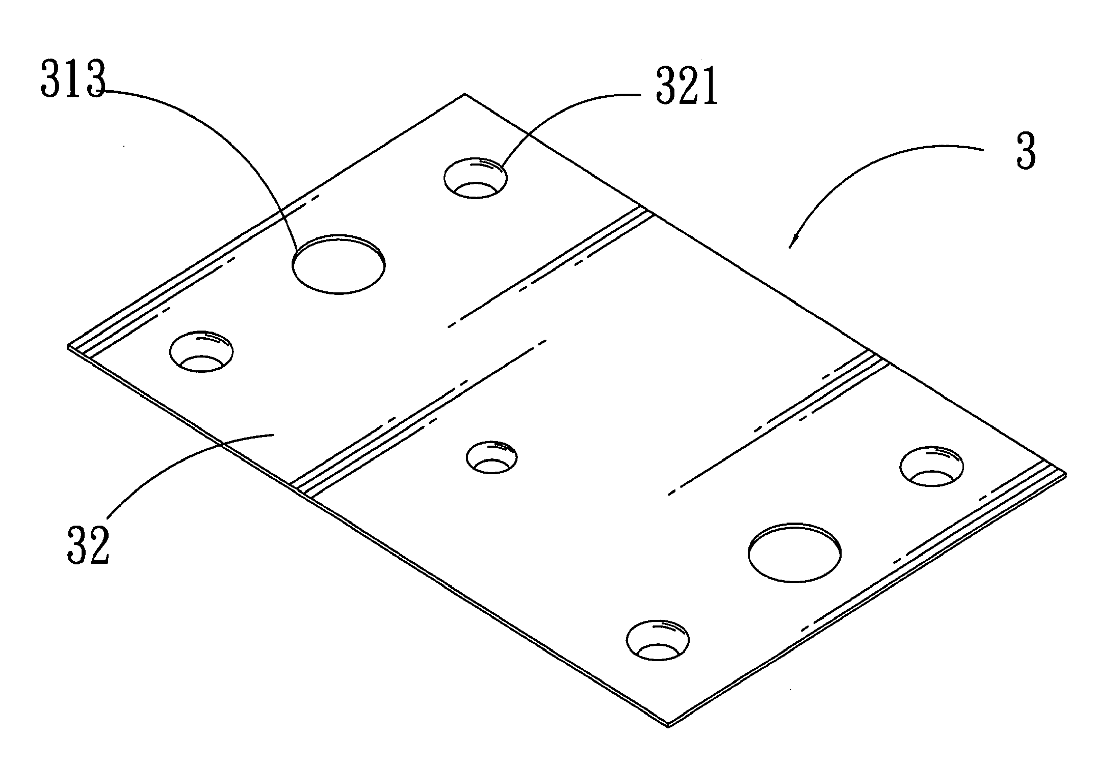
[0025]Please refer to FIGS. 3 and 4 that are rear and front perspective views, respectively, of a heat radiating fin according to the present invention; and to FIGS. 5 and 6 that are perspective and sectional views, respectively, showing the assembling of a plurality of the heat radiating fins into a heat sink. As shown, the heat radiating fin of the present invention, which is generally denoted a reference letter “A”, includes a flat body 3 having a front side 31 and a rear side 32, and is provided on the front side 31 at predetermined positions with a plurality of protruded portions 311 by way of stretching or drawing. The protruded portions 311 may have a suitable geometrical cross section, such as round, square, polygonal, or other shapes. Since the protruded portions 311 is formed by stretching to raise from the front side 31 of the flat body 3 of the heat radiating fin A by a predetermined distance, recessed portions 321 are formed on the rear side 32 of the flat body 3 corres...

third embodiment

[0030]FIG. 8 shows the present invention.

[0031]In the third embodiment, the protruded portions 311 are provided around the outer surface at a predetermined position with an annular rib 3113. When two flat bodies 3 are stacked with the protruded portions 311 on the first flat body 3 partially extended into the recessed portions 321 on the second flat body 3 located before the first flat body 3, the annular ribs 3113 on the protruded portions 311 are in contact with the inner rims 3211 of the recessed portions 321, enabling the two flat bodies 3 to be more tightly connected to each other while preventing the protruded portions 311 from excessively extending into the recessed portions 321 to assist the spacer protrusions 312 in maintaining the fixed spacing B.

[0032]FIG. 10 shows a fourth embodiment of the present invention. In the fourth embodiment, the protruded portions 311 are provided around the outer surface at a predetermined position with a plurality of spaced ribs 3114. When tw...


PUM


Abstract

A heat radiating fin includes a flat body having a front side and a rear side, a plurality of protruded portions formed on the front side of the flat body, and a plurality of recessed portions correspondingly formed on the rear side of the flat body behind the protruded portions. The protruded portions on the flat body of a first heat radiating fin are partially extendable into corresponding recessed portions on the flat body of a second heat radiating fin located before the first one, allowing the first and the second heat radiating fins to be easily and stably stacked.

Description

FIELD OF THE INVENTION[0001]The present invention relates to a heat radiating fin, and more particularly to heat radiating fins that can be easily manufactured to have enhanced structural strength and be stably stacked to form a heat sink.BACKGROUND OF THE INVENTION[0002]With the constantly developed technologies, many electronic elements in electronic apparatus and devices operate at an increasingly high speed and produce more heat than before. As a result, there is an urgent demand for an improved heat sink. A conventional heat sink usually includes a large number of stacked heat radiating fins to achieve an enhanced heat radiating and dissipating effect. Therefore, it has become an important task for the electronic industrial field to research and develop newer, more efficient, and cost-effective heat radiating fins.[0003]FIG. 1 shows a conventional heat radiating fin 1 and FIG. 2 shows the assembling of a plurality of the heat radiating fins 1 into a heat sink. As shown, the hea...

Claims


Application Information

Patent Timeline
Patent Type & Authority Applications(United States)
IPC IPC(8): F28F7/00
CPCH01L23/3672H01L23/427H01L2924/0002H01L2924/00
Inventor LIN, KUO-SHENG
Owner ASIA VITAL COMPONENTS SHENZHEN CO LTD
Why Eureka
Try Eureka