High voltage DC power generation

a dc power generation and high voltage technology, applied in the direction of control systems, electric generator control, dynamo-electric converter control, etc., can solve the problems of low power output power of the system, difficulty in properly rating the power system for low speed operation, and modulation of pulse width

Inactive Publication Date: 2012-05-24
HAMILTON SUNDSTRAND CORP
View PDF48 Cites 26 Cited by
  • Summary
  • Abstract
  • Description
  • Claims
  • Application Information

AI Technical Summary

Benefits of technology

[0004]According to one aspect of the invention, a DC power system includes a permanent magnet generator (PMG), and an active rectifier in electrical communication with the PMG. The active rectifier is adapted...

Problems solved by technology

However, system output power is limited if the back-electromotive force (BEMF) of the PMG is relatively low, which may result in difficulty properly rating a power system for low speed operation without increasing its size to account for higher current operation.
Furthermore, if the BEMF of the PMG is relatively high, pulse width modulated...

Method used


Image

  • High voltage DC power generation
  • High voltage DC power generation
  • High voltage DC power generation

Examples


Embodiment Construction

[0016]Embodiments of a DC power generating system are provided herein, with example embodiments being discussed below in detail.

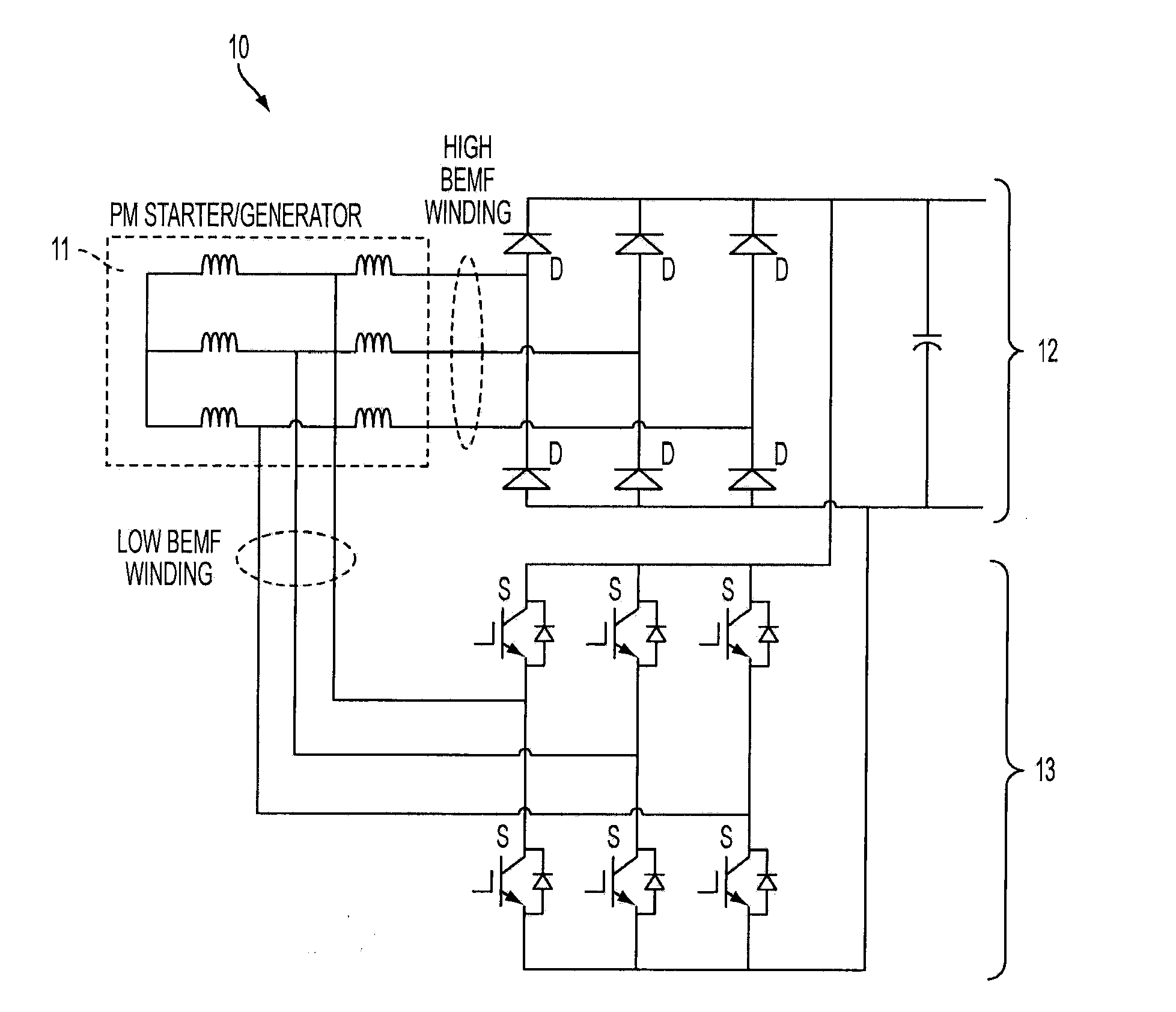
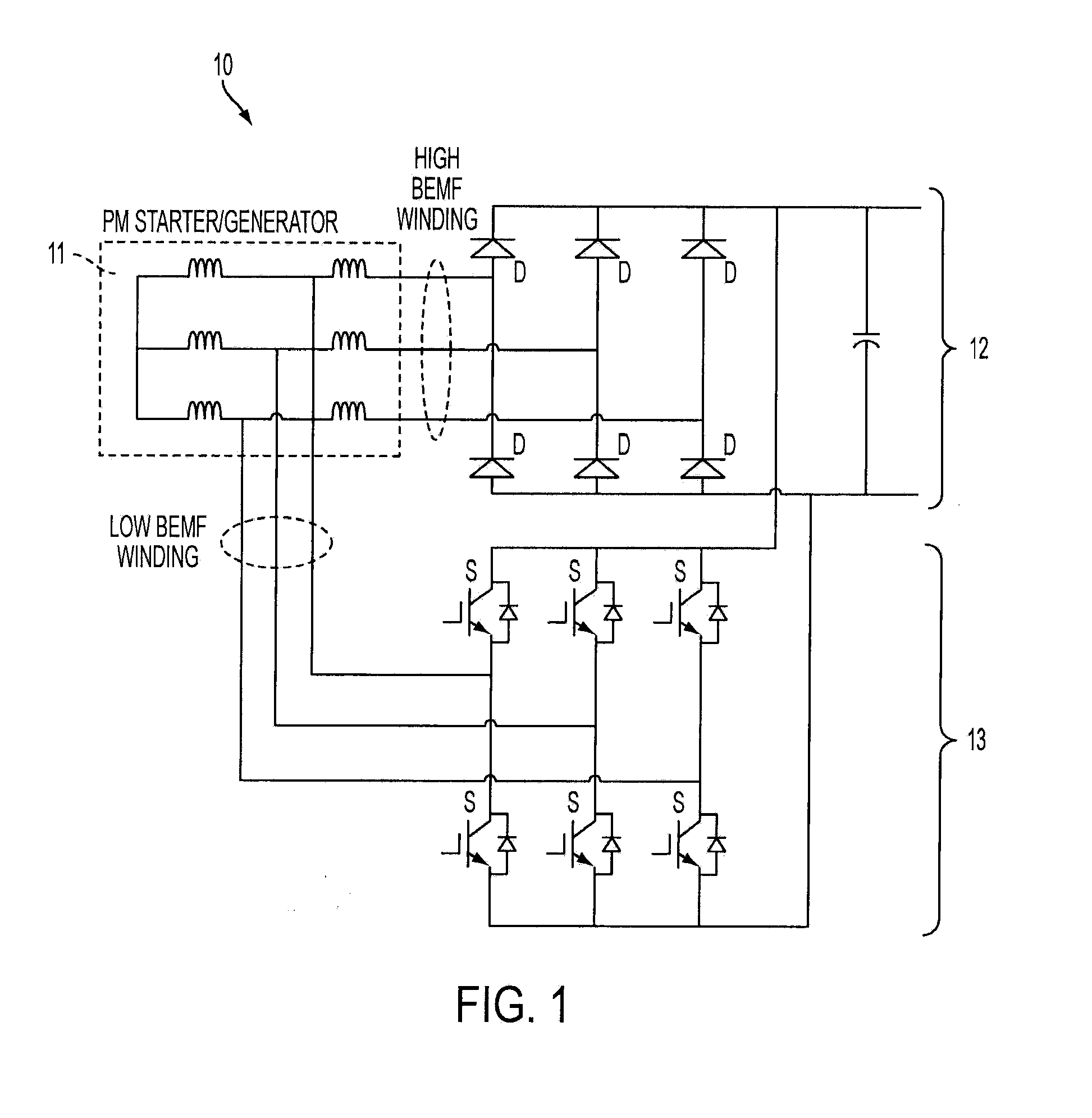
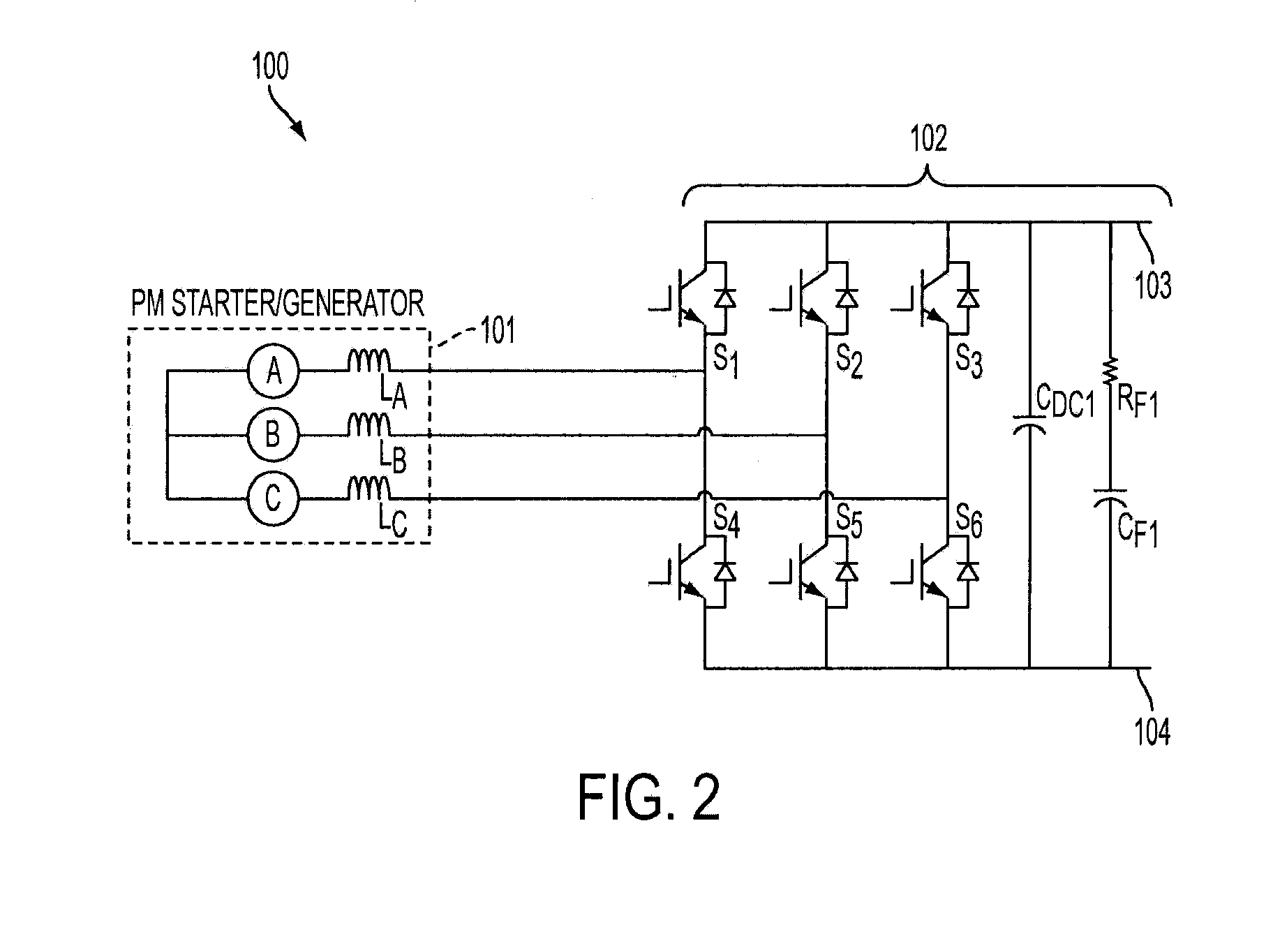
[0017]Turning to FIG. 2, a DC power system is shown. The DC power system 100 may be a power system of a vehicle (e.g., ground vehicle, marine vehicle, aircraft, etc.). As illustrated, the system 100 includes a permanent magnet generator (PMG) and / or permanent magnet starter 101. The PMG 101 may be a synchronous generator, and may produce 3-phase power (denoted with phases A, B, and C) across three windings (denoted LA, LB, and LC).

[0018]The system 100 further active rectifier 102 in electrical communication with PMG 101, for example, through the windings LA, LB, and Lc. The active rectifier 102 includes a plurality of switches S1, S2, S3, S4, S5, and S6 configured to switch on / off in response to pulse width modulated (PWM) signals applied from a controller or gate driver (not illustrated). Each switch of the plurality of switches S1, S2, S3, S4, S5, and S6 ...


PUM


Abstract

A DC power system includes a permanent magnet generator (PMG), and an active rectifier in electrical communication with the PMG. The active rectifier is adapted to actively rectify power output from the PMG if the PMG is operating at low speed, and the active rectifier is further adapted to passively rectify power output from the PMG if the PMG is operating at high speed.

Description

FIELD OF INVENTION[0001]The subject matter disclosed herein relates generally to the field of power systems, and more particularly to high voltage direct current (DC) power generation with active rectification.DESCRIPTION OF RELATED ART[0002]Generally, current requirements for loads on a power system dictate the size, weight, and cost of said system. In power systems utilizing permanent magnet generators (PMG) and / or permanent magnet starters, an ideal balance would include a PMG-based power system capable of producing large torque ratings with minimal current at low speed, while also being capable of regulating DC output voltage at higher speeds. However, system output power is limited if the back-electromotive force (BEMF) of the PMG is relatively low, which may result in difficulty properly rating a power system for low speed operation without increasing its size to account for higher current operation. Furthermore, if the BEMF of the PMG is relatively high, pulse width modulated...

Claims


Application Information

Patent Timeline
IPC IPC(8): H02P9/48
CPCH02P9/48H02P9/307H02P25/22
Inventor FANG, SI J.HIMMELMANN, RICHARD A.MOSS, STEVEN J.ROZMAN, GREGORY I.
Owner HAMILTON SUNDSTRAND CORP
Why Eureka
Try Eureka