Sensor Assembly And Methods Of Assembling A Sensor Probe

a sensor and assembly technology, applied in the field of power systems, can solve the problems of complex manufacturing steps and/or machinery, known machines may exhibit vibration and/or other abnormal behavior, and the manufacturing process may be expensiv

Inactive Publication Date: 2012-05-24
GENERAL ELECTRIC CO
View PDF8 Cites 38 Cited by
  • Summary
  • Abstract
  • Description
  • Claims
  • Application Information

AI Technical Summary

Problems solved by technology

Known machines may exhibit vibrations and / or other abnormal behavior during operation.
However, such a fabrication process may be expensive and / or may involve complicated manufacturing steps and / or machinery.
Moreover, because the unit is an integrated component, if one element of the proximity sensor is faulty or damaged, the entire sensor may need to be replaced.

Method used


Image

  • Sensor Assembly And Methods Of Assembling A Sensor Probe
  • Sensor Assembly And Methods Of Assembling A Sensor Probe
  • Sensor Assembly And Methods Of Assembling A Sensor Probe

Examples


Embodiment Construction

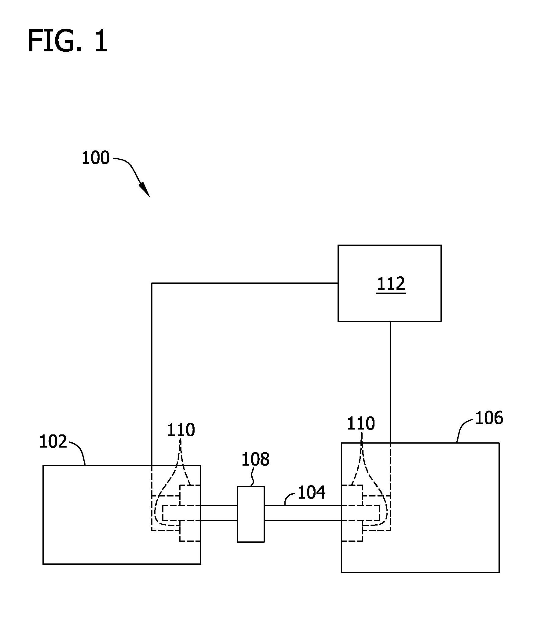
[0011]FIG. 1 shows an exemplary power system 100 that includes a machine 102. In the exemplary embodiment, machine 102 may be, but is not limited to only being, a wind turbine, a hydroelectric turbine, a gas turbine, or a compressor. Alternatively, machine 102 may be any other machine used in a power system. In the exemplary embodiment, machine 102 rotates a drive shaft 104 that is coupled to a load 106, such as a generator.

[0012]In the exemplary embodiment, drive shaft 104 is at least partially supported by one or more bearings (not shown) housed within machine 102 and / or within load 106. Alternatively or additionally, the bearings may be housed within a separate support structure 108, such as a gearbox, or within any other structure or component that enables power system 100 to function as described herein.

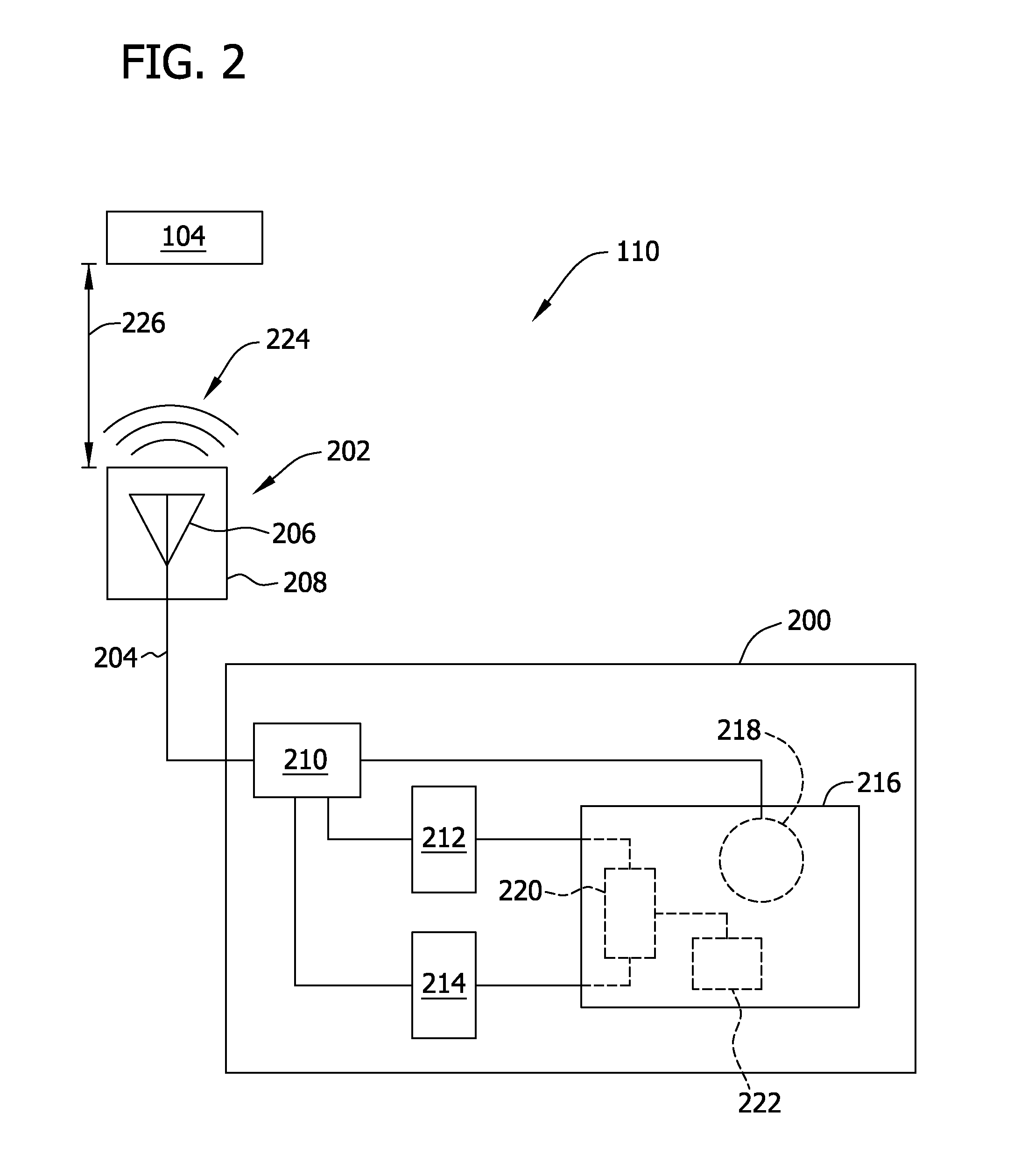
[0013]In the exemplary embodiment, power system 100 includes at least one sensor assembly 110 that measures and / or monitors at least one operating condition of machine 102, of d...


PUM

PropertyMeasurementUnit
electromagnetic fieldaaaaaaaaaa
microwaveaaaaaaaaaa
non-conductiveaaaaaaaaaa

Abstract

A method of assembling a sensor probe includes positioning an emitter within a probe cap, wherein the emitter is configured to generate an electromagnetic field from at least one microwave signal. An inner sleeve is coupled to the probe cap and an outer sleeve is coupled to the inner sleeve.

Description

BACKGROUND OF THE INVENTION[0001]The present application relates generally to power systems and, more particularly, to a sensor assembly and methods of assembling a sensor probe.[0002]Known machines may exhibit vibrations and / or other abnormal behavior during operation. One or more sensors may be used to measure and / or monitor machine operation and to determine, for example, an amount of vibration exhibited in a machine drive shaft, a rotational speed of the machine drive shaft, and / or any other suitable operational characteristic of an operating machine or motor. Often, known sensors are coupled to a machine monitoring system that includes a plurality of monitors. The monitoring system receives signals representative of measurements from one or more sensors, performs at least one processing step on the signals, and then transmits the modified signals to a diagnostic platform that displays the measurements to a user.[0003]At least some known machines use one or more proximity sensor...

Claims


Application Information

Patent Timeline
Patent Type & Authority Applications(United States)
IPC IPC(8): G01N22/00B23P11/00
CPCG01D5/48Y10T29/49826G01H9/00G01D11/245
Inventor JENSEN, RAYMONDSHEIKMAN, BORIS LEONID
Owner GENERAL ELECTRIC CO
Why Eureka
Try Eureka