Radar device

a technology of radar and front object, applied in measurement devices, multi-channel direction-finding systems using radio waves, instruments, etc., can solve the problems of inability of radar devices to analyze and determine the type of each front object, and inability to determine what the detected front object is, and achieve the effect of superior radar devices

Active Publication Date: 2012-05-24
DENSO CORP
View PDF10 Cites 22 Cited by
  • Summary
  • Abstract
  • Description
  • Claims
  • Application Information

AI Technical Summary

Benefits of technology

[0023]The radar device according to the exemplary embodiment of the present invention having the above structure and functions can judge the type of the object on the basis of the arrival echoes from the objects as the detection targets. Accordingly, when a motor vehicle is equipped with the radar device, it is possible to determine a type of an object present in the area around of the motor vehicle. Further, it is possible for the motor vehicle to execute various safety processes on the basis of the judgment results of the radar device, which are not executed by a motor vehicle equipped with a conventional radar device. For example, the ECU in the motor vehicle equipped with the radar device according to the exemplary embodiment of the present invention can switch the driving processes on the basis of the type of the front object as the judgment results of the radar device. Thus, the present invention provides a superior radar device when compared with the conventional radar devices.

Problems solved by technology

However, the conventional radar devices cannot analyze and determine a type of each front object, for example, cannot determine what the detected front object is, for example a stopped motor vehicle, a running motor vehicle, standing human, walking human, a guard rail, or a traffic sign board.

Method used


Image

  • Radar device
  • Radar device
  • Radar device

Examples


first exemplary embodiment

[0036]A description will be given of the radar device 1 according to an exemplary embodiment of the present invention with reference to FIG. 1 to FIG. 6.

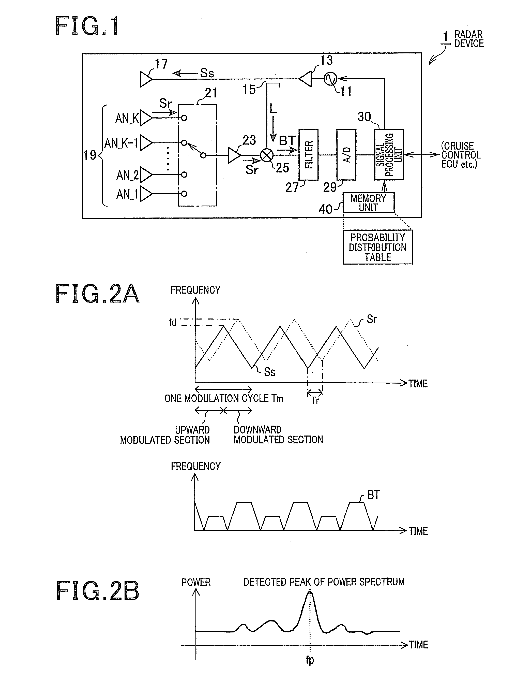
[0037]FIG. 1 is a block diagram schematically showing a configuration of the radar device 1 according to the exemplary embodiment of the present invention.

[0038]The radar device 1 is a frequency modulated continuous wave (FMCW) radar device mounted on a motor vehicle. The FMCW radar device transmits radar wave in FMCW format and receives echoes as reflected radar waves. As shown in FIG. 1, the FMCW radar device 1 is comprised of an oscillator 11, an amplifier 13, and a distributor 15 and a transmitting antenna 17.

[0039]The oscillator 11 generates a millimeter high frequency signal. The millimeter high frequency is linearly changed, namely increased and decreased according to a time elapse. The amplifier 13 amplifies the millimeter high frequency signal generated by the oscillator 11. The distributor 15 distributes the millimeter hig...

first modification

[0135]FIG. 7 is a view showing a structure of a radar device 2 as a modification of the radar device 1 shown in FIG. 1.

[0136]In the radar device 2 as a modification of the radar device 1 shown in FIG. 1, a memory unit 41 stores a compensation table in addition to the probability distribution table, a signal processing unit 31 communicates with a navigation ECU 100 through an on-vehicle local area network (on-vehicle LAN), and the signal processing unit 31 executes a target object estimation process which is different from the target object estimation process shown in FIG. 6. The signal processing unit 31 corresponds to the signal processing unit 30 shown in FIG. 1, and the memory unit 41 corresponds to the memory unit 40 shown in FIG. 1.

[0137]Other components of the signal processing unit 31 are the same of those in the signal processing unit 30. The explanation of the same components is omitted here and the different features of the radar device 2 from the radar device 1 shown in F...

second modification

[0166]A description will now be given of a radar device 3 according to a second modification with reference to FIG. 9.

[0167]FIG. 9 is a flow chart showing a part of the target object estimation process as other modification of the target object estimation process shown in FIG. 6.

[0168]In the radar device 3 according to the second modification of the radar device 1, a signal processing unit 32 receives speed information of the own motor vehicle from a speed sensor 105 shown in FIG. 9, instead of the category of the road environmental information through the navigation ECU 100. Further, the signal processing unit 32 executes the target object estimation process shown in FIG. 9, which is different from the target object estimation process shown in FIG. 6.

[0169]Other components of the signal processing unit 32 are the same as those in the signal processing unit 30. The explanation of the same components is omitted here and the different features of the radar device 3 from the radar devi...


PUM


Abstract

A signal processing unit in a radar device calculates a change amount Y (=log(P)−log(Pb)) between a power P of a current arrival echo and a power of a previous arrival echo arrived before an observation period TSW. A memory unit in the radar device stores, every type of objects, a probability distribution of the change amount Y calculated from the arrival echo from the object. On the basis of the calculated change amount Y and the probability distribution, the signal processing unit determines a probability Pr to obtain the change amount Y every type of object, and determines that the object having the maximum probability Pr is the object which transmits the current arrival echo.

Description

CROSS-REFERENCE TO RELATED APPLICATION[0001]This application is related to and claims priority from Japanese Patent Application No. 2010-259070 filed on Nov. 19, 2010, the contents of which are hereby incorporated by reference.BACKGROUND OF THE INVENTION[0002]1. Field of the Invention[0003]The present invention relates to radar devices.[0004]2. Description of the Related Art[0005]There are various radar devices which are widely used in various applications, for example, a motor vehicle field. Such a radar device emits radio waves from a transmitting antenna and receives echoes (reflected radar waves) reflected by objects as detection targets through a receiving antenna array. There is a front running vehicle as a front object as a detection target. Such a conventional radar device detects a distance between an own motor vehicle equipped with the radar device and an object on the basis of a time difference (delay) between a time of transmitting a radio wave and an arrival time of eac...

Claims


Application Information

Patent Timeline
Patent Type & Authority Applications(United States)
IPC IPC(8): G01S13/00G01S13/42G01S13/931
CPCG01S3/74G01S7/412G01S13/345G01S13/584G01S2013/9375G01S13/34G01S13/42G08G1/16G01S2013/9353G01S13/931G01S2013/932G01S2013/93271
Inventor WATANABE, YUUSUZUKI, KOICHIROYAMANO, CHIHARU
Owner DENSO CORP
Why Eureka
Try Eureka