
Stereo video capture system and method

a stereo video and capture system technology, applied in steroscopic systems, picture processing, electrical equipment, etc., can solve the problems of large manual corrections, inability to achieve the desired parallax of captured stereo video images, and limited hardware availability of conventional stereo video capture systems

Active Publication Date: 2012-05-24
SUPERD TECH CO LTD
View PDF2 Cites 15 Cited by
  • Summary
  • Abstract
  • Description
  • Claims
  • Application Information

AI Technical Summary

Benefits of technology

[0068]By automatically converting parallax-related parameters associated with 3D images in real-time, the disclosed systems and methods may make easy for photographers to obtain desired 3D video images while capturing the 3D video images, thus avoid after-capture parallax correction and may significantly increase efficiency.

Problems solved by technology

Conventional stereo video capture systems are often limited by available hardware.
When using these conventional systems to capture stereo video images based on parallax, a large amount of manual corrections may be needed.
So, in many cases, the captured stereo video images may not have a desired parallax.
An undesired parallax associated with stereo video images likely causes a viewer some discomfort when watching the stereo video images.
Further, if the captured video image has an undesired parallax, the stereo video images may need to be corrected later, or may need to be captured later, which may result in waste of time and resources.
However, when a user finds low quality stereo video images, the user needs to manually adjust the stereo camera based on the user's experience.
Further, because the significant size-difference between the stereo video monitor's small monitor screen and a large screen for displaying the stereo video images to a viewer(s), it is difficult to detect certain undesired parallax that may appear in the large screen while watching the stereo video images on the small monitor screen.

Method used


Image

  • Stereo video capture system and method
  • Stereo video capture system and method
  • Stereo video capture system and method

Examples


Embodiment Construction

[0020]Reference will now be made in detail to exemplary embodiments of the invention, which are illustrated in the accompanying drawings. Wherever possible, the same reference numbers will be used throughout the drawings to refer to the same or like parts.

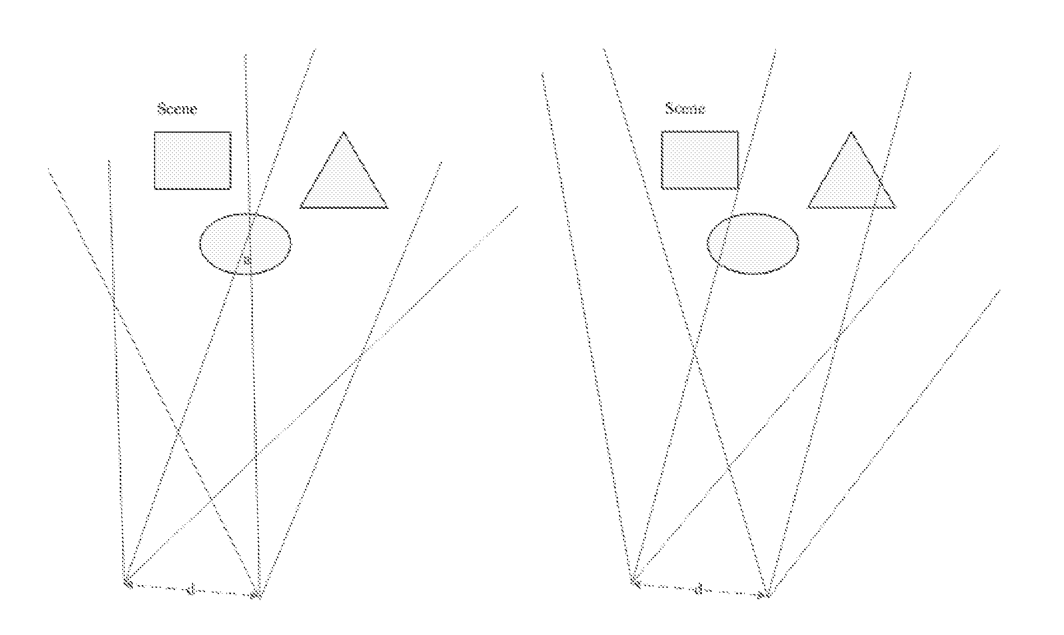
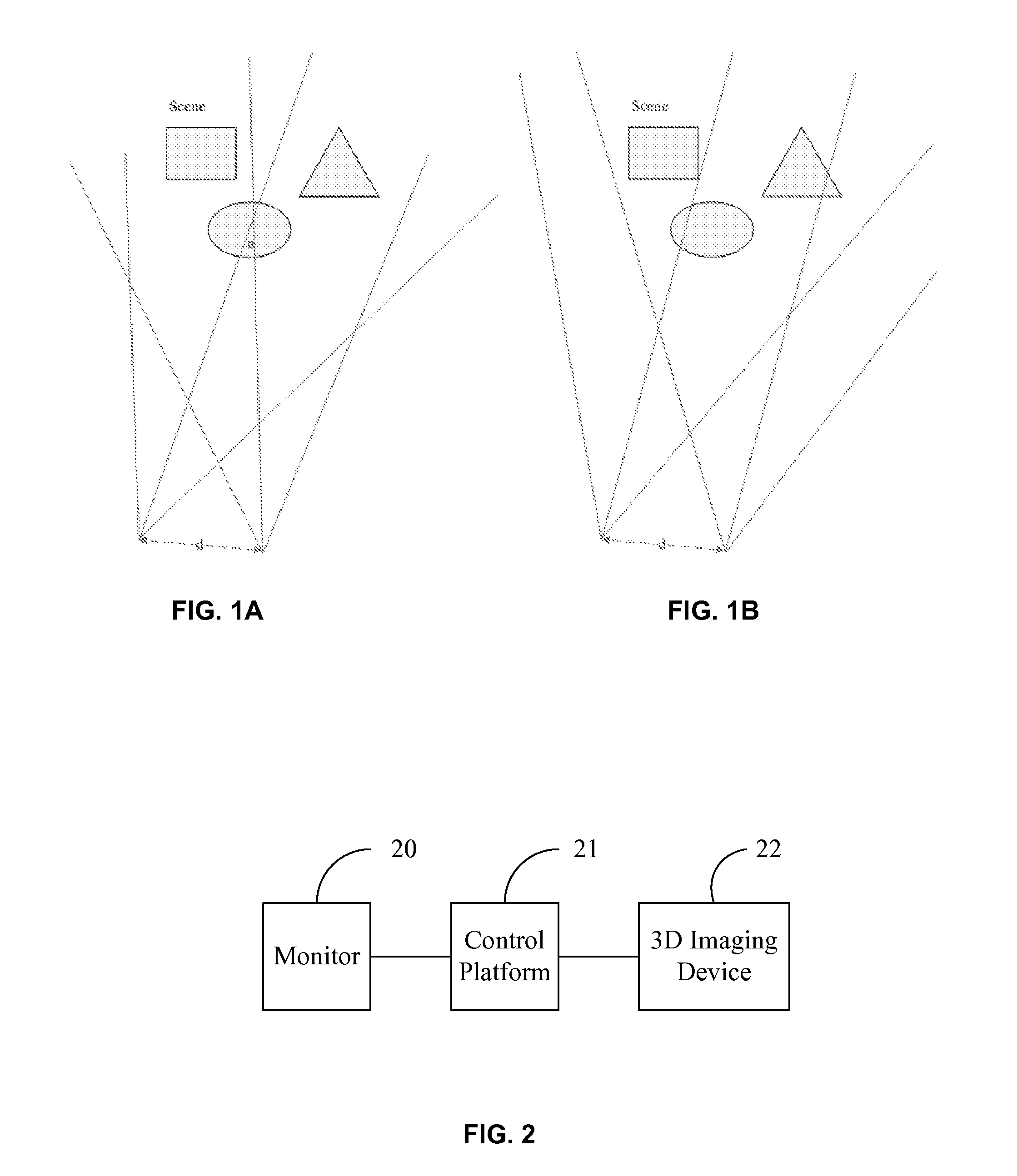
[0021]FIG. 2 illustrates an exemplary stereo video capture system 200. As shown in FIG. 2, stereo video capture system 200 includes a stereo video monitor 20, a control platform 21, and a 3D imaging capture device 22. Other components or devices may be added without departing the principles of the disclosed embodiments. Stereo video capture system 200 is capable of taking stereo or three-dimensional (3D) video images using 3D imaging capture device 22. A 3D image includes at least an image to be viewed by a viewer's left eye (i.e., the left image) and an image to be viewed by the viewer's right eye (i.e., the right image). A certain parallax or disparity exists between the left image and the right image such that the viewer can per...


PUM


Abstract

A method is provided for a stereo video capture system. The stereo video system includes a stereo video monitor, a control platform, and a three-dimensional (3D) capture imaging device. The method includes capturing at least a first image and a second image, with a parallax between the first image and the second image based on a first parallax configuration. The method also includes receiving the first and second images; and calculating a value of at least one parallax setting parameter associated with the first and second images and corresponding to the first parallax configuration. Further, the method includes determining whether the value is within a pre-configured range. When the value is out of the pre-configured range, the method includes converting the first parallax configuration into a second parallax configuration. The method also includes sending, the second parallax configuration to the 3D imaging capture device, and adopting the second parallax configuration in operation.

Description

CROSS-REFERENCES TO RELATED APPLICATIONS[0001]This application claims the priority of PCT patent application no. PCT / CN2010 / 079004, filed on Nov. 23, 2010, the entire contents of which are incorporated herein by reference.FIELD OF THE INVENTION[0002]The present invention generally relates to video capture systems and, more particularly, to the methods and systems for stereo video capture and stereo three-dimensional (3D) display.BACKGROUND[0003]Conventional stereo video capture systems are often limited by available hardware. When using these conventional systems to capture stereo video images based on parallax, a large amount of manual corrections may be needed. Sometimes, it even requires repeated manual attempts before a video capture system can operate at a reasonable quality level. So, in many cases, the captured stereo video images may not have a desired parallax. An undesired parallax associated with stereo video images likely causes a viewer some discomfort when watching the...

Claims


Application Information

Patent Timeline
IPC IPC(8): H04N13/02H04N13/239
CPCH04N13/0296H04N13/0239H04N13/296H04N13/239
Inventor SONG, LEI
Owner SUPERD TECH CO LTD
Learn More