
Method For Transmitting Signals, User Equipment Thereof

Active Publication Date: 2012-05-24
ZTE CORP
View PDF11 Cites 3 Cited by
  • Summary
  • Abstract
  • Description
  • Claims
  • Application Information

AI Technical Summary

Benefits of technology

[0010]Preferably, the UE selects a pre-coding matrix which enables the noise of a layer of signal with good channel to be minimized from a plurality of pre-coding matrices according to the following formula: i=arg min(min(c(i)00,c(i)11)), wherein i is the index number of a pre-coding matrix, min represents taking the minimum value, arg min represents the value of i that minimizes min(c(i)00,c(i)11).
[0012]Preferably, the UE selects a pre-coding matrix which enables the noise of a layer of signal with poor channel to be minimized from a plurality of pre-coding matrices according to the following formula: i=arg min(max(c(i)00,c(i)11)), wherein i is the index number of a pre-coding matrix, max represents taking the maximum value, arg min represents the value of i that minimizes the value of max(c(i)00,c(i)11).

Problems solved by technology

However, these methods are inapplicable when the number of transmission antennas is equal to that of the layers of the transmission signal.
The performance of this algorithm is relatively poor when being applied in an LTE system when the number of transmission antennas is equal to that of the signal layers.
Although it is possible for a layer of signal with low MSE to pass through when the spatial characteristics of the channel are poor, it would cause another layer with high MSE to be received in error when the spatial characteristics of the channels are good.
However, in practical application, it is often difficult to decide when to use the maximized MSE difference method and when to use the even MSE method.
That is, it is difficult to select the better pre-coding matrix.
Therefore, the system performance is compromised.

Method used


Image

  • Method For Transmitting Signals, User Equipment Thereof
  • Method For Transmitting Signals, User Equipment Thereof
  • Method For Transmitting Signals, User Equipment Thereof

Examples


Embodiment Construction

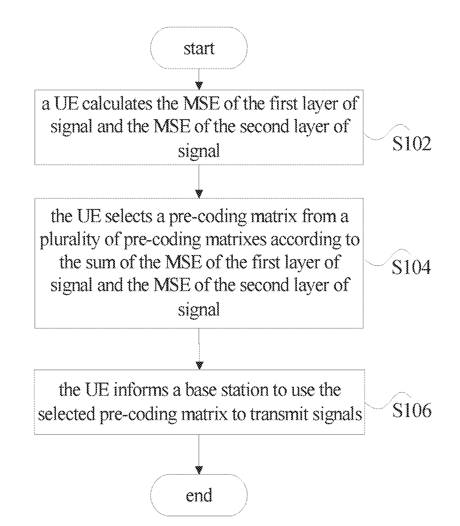
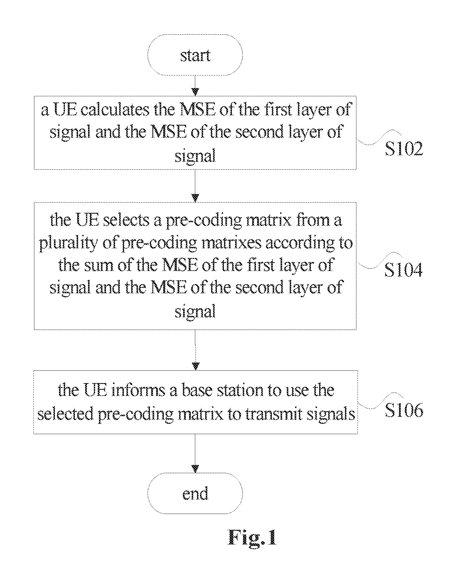
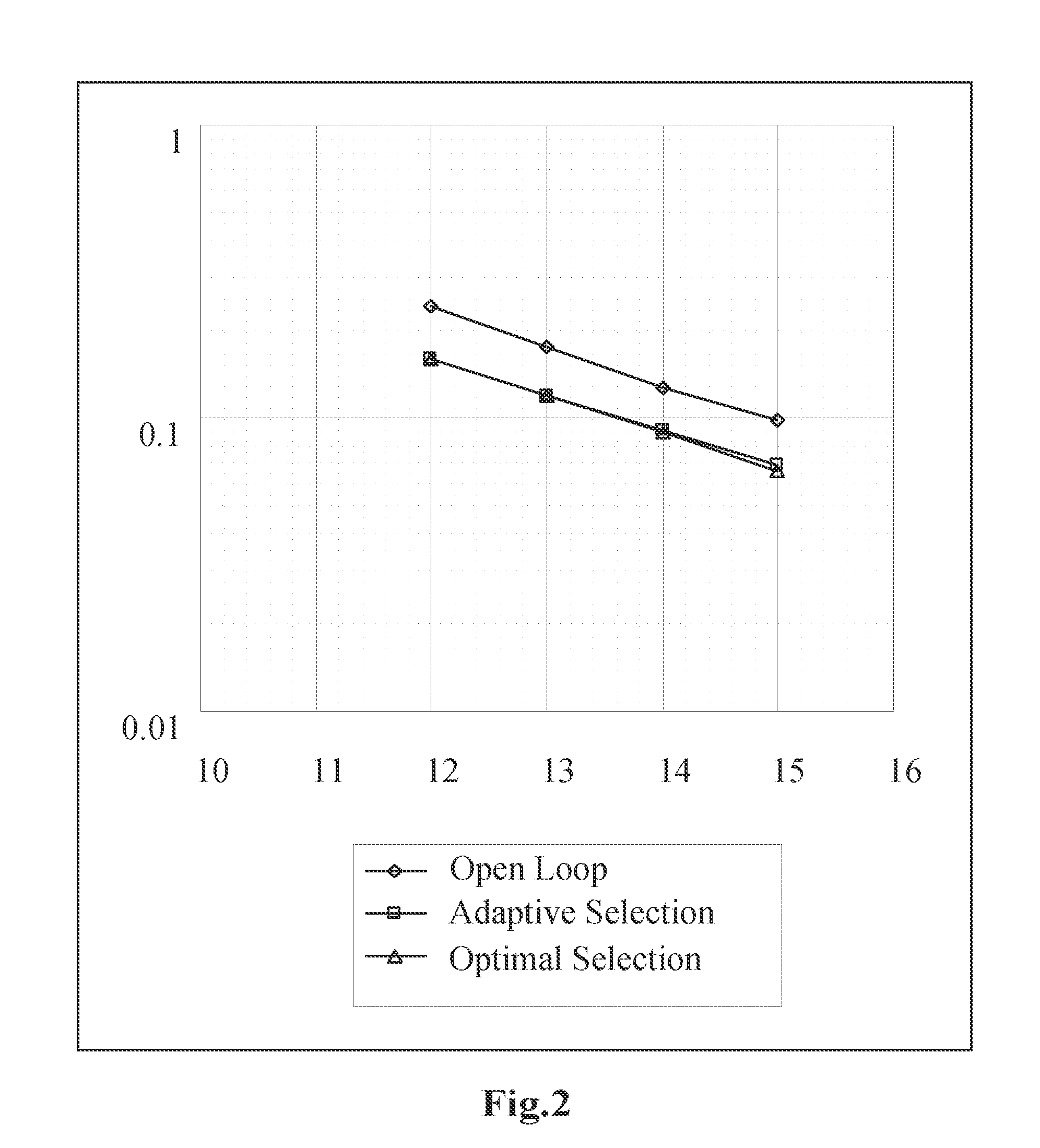
[0025]The embodiments of the present invention provide a solution for signal transmission, and during implementation, it is found that the sums of the MSEs of two layers of signal of the minimum mean squared error (MMSE) receiver are the same and different pre-coding matrices cause different distributions of the MSE between 2 layers of signal, the MSEs of these 2 layers of signal are used as the criterion of selecting a pre-coding matrix, i.e. the pre-coding matrix is selected according to the spatial characteristics of the channels. The processing principles are as follows: calculate the MSE of the first layer of signal and the MSE of the second layer of signal in two layers of signal; and select a pre-coding matrix from a plurality of pre-coding matrices according to the sum of the MSE of the first layer of signal and the MSE of the second layer of signal so that a base station transmits signals according to the selecting pre-coding matrix. By way of this embodiment, the MSE is mo...


PUM


Abstract

The present invention discloses a method for signal transmission and a user equipment (UE), wherein said method comprises: user equipment UE calculating an MSE of a first layer of signal and an MSE of a second layer of signal; the UE selecting a pre-coding matrix from a plurality of pre-coding matrices according to the sum of the MSE of the first layer of signal and the MSE of the second layer of signal; and the UE informing a base station to use the selected pre-coding matrix to transmit signals. By way of the present invention, the correct transmission of signals is ensured, the block error rate of the system is reduced, and the throughput of the system is improved.

Description

FIELD OF THE INVENTION[0001]The present invention relates to the communication field, and in particular to a method for signal transmission and a user equipment (UE).BACKGROUND OF THE INVENTION[0002]The multiple antennae input multiple antennae output (abbreviated as MIMO) technology is a key technology of the 3rd Generation (abbreviated as 3G), 4th Generation (abbreviated as 4G), and even the future broadband wireless communication. The MIMO technology can be divided into two categories: open loop MIMO technology and closed loop MIMO technology. The closed loop MIMO technology can significantly improve the system capacity, but it needs to obtain the information of the transmission channels. In the closed loop MIMO technology, the transmitters select suitable transmission modes according to the characteristics of the transmission channels.[0003]In the LTE protocol, when the user equipment (abbreviated as UE) works in closed loop MIMO mode with space multiplexing, the UE needs to sel...

Claims


Application Information

Patent Timeline
IPC IPC(8): H04L27/00
CPCH04L25/03343H04B7/0456H04B7/08H04L1/06
Inventor REN, TIANMIN
Owner ZTE CORP
Learn More