
Method and device for automatic buoyancy compensation for a scuba diver or underwater device while in any orientation

a technology of automatic buoyancy compensation and underwater equipment, applied in underwater equipment, waterborne vessels, transportation and packaging, etc., can solve the problems of increasing the effort level of divers, increasing the risk of injury or death, and increasing the difficulty of divers to adjust the buoyancy. , to achieve the effect of reducing the effort level of divers, increasing safety, and conserving air

Inactive Publication Date: 2012-05-24
WALCK JEFFREY ALAN
View PDF10 Cites 19 Cited by
  • Summary
  • Abstract
  • Description
  • Claims
  • Application Information

AI Technical Summary

Benefits of technology

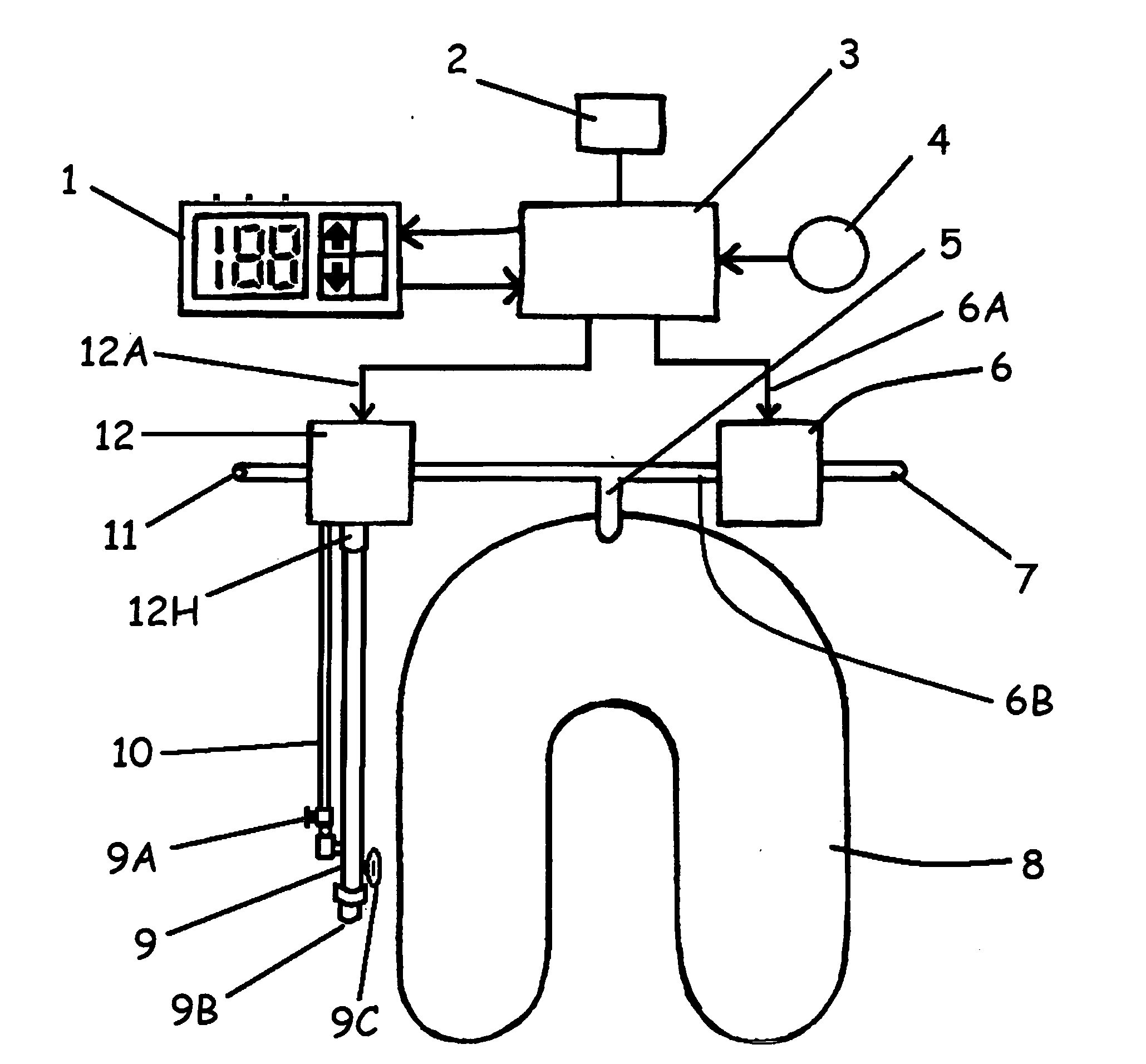
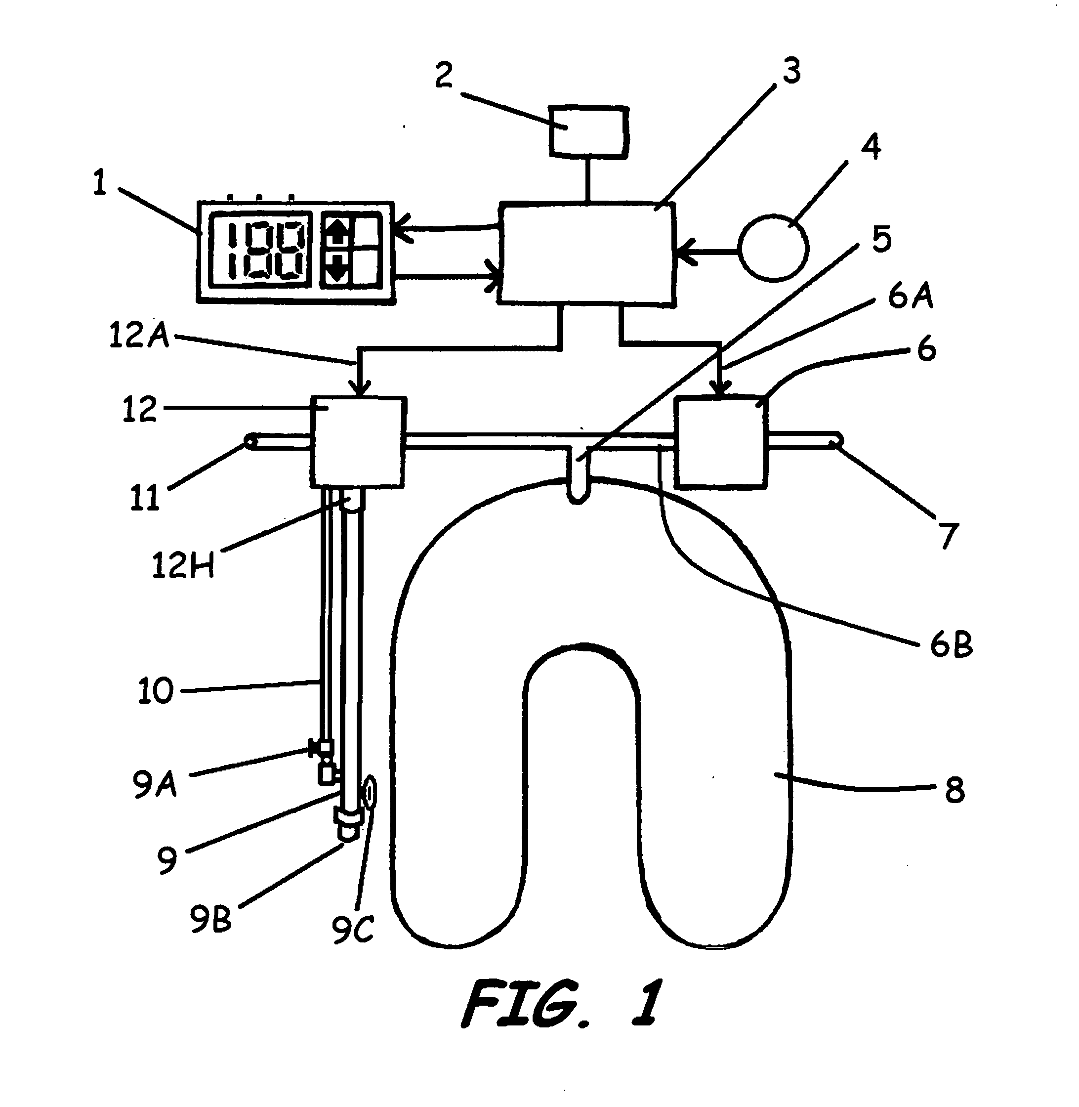
[0016]A motor-driven evacuation pump or a valve-controlled venturi may further be actuated by an electronic controller. This controller also controls a valve for adding air to the bladder. Thus, the controller is capable of establishing a desired amount of air in the bladder, and of subsequently increasing or decreasing that amount. The controller is connected to a pressure transducer for the purpose of determining the current water depth. The controller also receives control settings from an arrangement of switches, knobs, joysticks, or other control inputs. The combination of control inputs and depth information allows a predetermined depth to be achieved and maintained by the controller, independent of human interaction. Some of the components described, such as valves, hoses, manifold, and pressure transducer may replace similar components in standard diving equipment, that is, diving equipment unmodified by the present invention. Conversely, the components typical of standard diving equipment may be kept intact for redundancy and thus augmented by the additional capabilities of the present invention.

Problems solved by technology

Failure to do so risks plummeting deeper at an increasing rate or rising at an ever increasing rate, either of which may result in injury or death.
For example, as the dive progresses, the diver's compressed air tank becomes depleted, resulting in a lightening of said tank and an increase in buoyancy.
This reduced volume reduces the effect of the positive buoyancy which tends to make the diver sink, which decreases the volume of the compressible positive buoyancy further, resulting in the tendency to sink at an ever increasing rate.
A diver who begins to sink and fails to check his decent risks any numbers of hazards, such as ear damage, nitrogen narcosis, decompression sickness (“the bends”), asphyxiation and ultimately death.
A diver that ascends unchecked risks air embolism, damaged lungs and sinuses, decompression sickness and, again, death.
Both this skill and the proper adjustment of BCDs require considerable training and practice.
Adding to the difficulty in perfecting such skill is the fact that the diver must compensate for the buoyancy of his body and equipment while in any orientation during the dive.
Buoyancy compensation for underwater vehicles or for devices not under human control is particularly difficult.
Although the same tendency to sink or rise occurs with such a device, there is no human present to adjust the amount of buoyancy.
For example, if said valve is below (at a greater depth than) a pocket of air trapped in the life jacket, the valve will be useless in venting air out of the life jacket.
This is because the secluded air will tend toward the surface while the valve, situated at a greater depth, is incapable of providing a means for the air to escape the life jacket.

Method used


Image

  • Method and device for automatic buoyancy compensation for a scuba diver or underwater device while in any orientation
  • Method and device for automatic buoyancy compensation for a scuba diver or underwater device while in any orientation
  • Method and device for automatic buoyancy compensation for a scuba diver or underwater device while in any orientation

Examples


Embodiment Construction

[0026]The present invention discloses a novel method for automatic buoyancy compensation of any underwater object, including a human diver. The preferred embodiment allows the diver to control the automatic buoyancy compensator via control inputs. In addition, any of a number of means to communicate status back to the diver (visual, auditory, tactile) may be employed to inform the diver of current conditions and thus facilitate the diver's control of the apparatus.

[0027]FIG. 1 shows a schematic representation of a preferred embodiment of the entire buoyancy compensation system intended to be worn and used by a human diver. Display / input module 1 allows the diver to provide control inputs to control module 3 and to observe status information produced by control module 3. The flow of control settings and status information are indicated, respectively, by the arrows from display / input module 1 to control module 3 and from control module 3 to display / input module 1. Control module 3 may...


PUM


Abstract

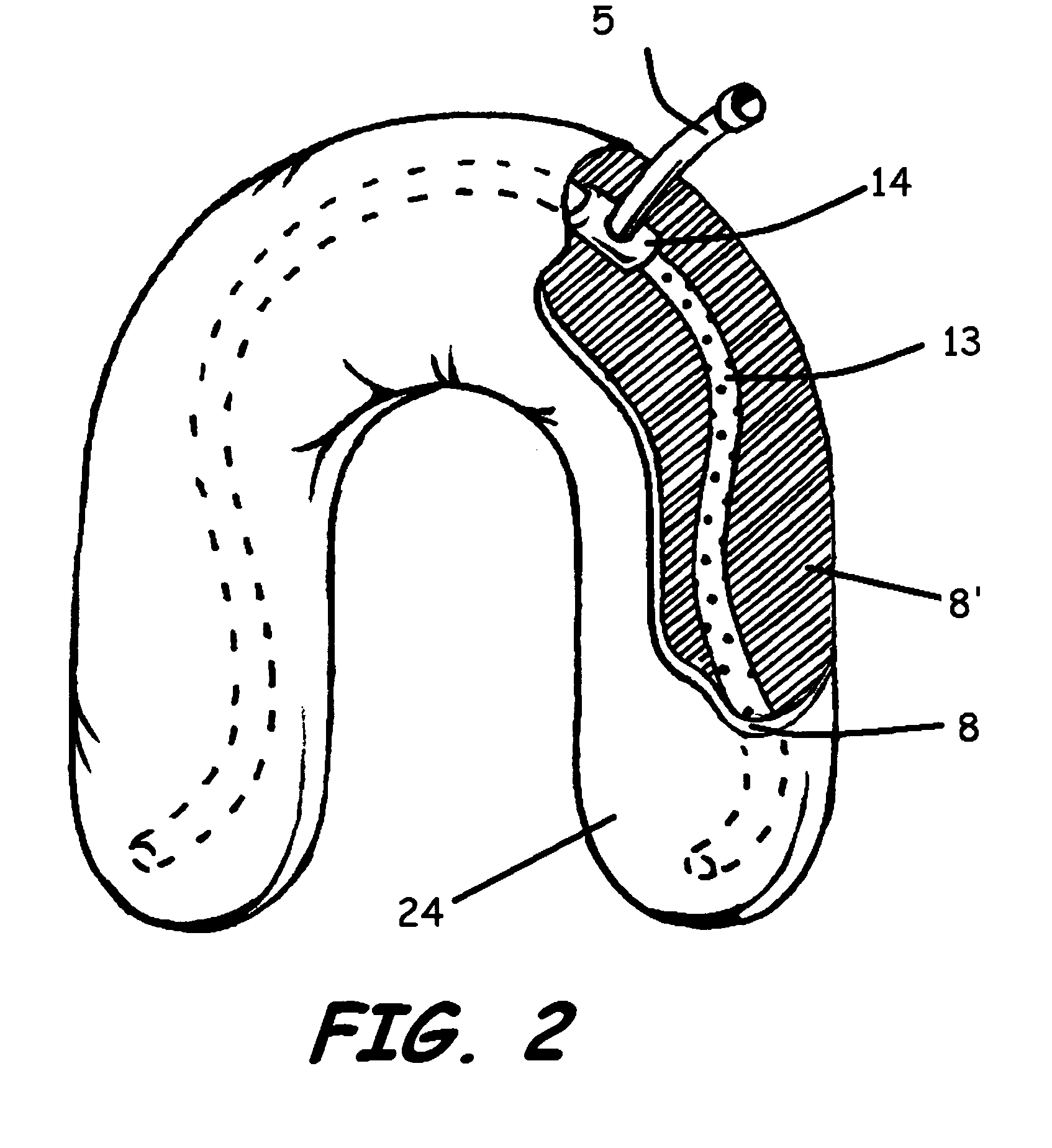
A buoyancy compensation device and method for a scuba diver or other underwater object, which decreases buoyancy by actively pumping air from a flexible bladder while the diver or object is in any orientation, said bladder having internally a manifold assembly providing access to pockets of air anywhere within the bladder. In addition, said device and method may be adapted for automatically diving, surfacing, or maintaining a predetermined water depth while the diver or object is in any orientation and while the diver's or object's orientation changes, including a sensor for measuring water depth, one or more control inputs for selecting a depth, and a controller unit that determines descent rate, ascent rate, or maintenance of a selected depth based on monitoring the water depth, the setting of the control inputs, and the diver's or objects previous habits and behavior.

Description

CROSS REFERENCE TO RELATED APPLICATION[0001]This application claims priority to provisional application 61 / 458,137 filed on Nov. 18, 2010.STATEMENT REGARDING FEDERALLY SPONSORED RESEARCH OR DEVELOPMENT[0002]Not applicable.REFERENCE TO A SEQUENCE LISTING, A TABLE, OR A COMPUTER PROGRAM LISTING COMPACT DISK APPENDIX[0003]Not applicable.FIELD OF THE INVENTION[0004]The invention pertains to scuba diving equipment. Specifically, the invention pertains to automatic buoyancy compensation for a scuba diver or underwater device.BACKGROUND OF THE INVENTION[0005]Scuba divers, deep sea divers, and other submarine applications most easily maintain a fixed depth by anchoring themselves to a submerged fixture or connecting to a tether from the surface. Lacking such an anchor or tether requires continuously adjusting the buoyancy of the diver or object to maintain a specific depth. In particular, scuba divers are required to learn to carefully “balance” atop a parabolic buoyancy equilibrium curve w...

Claims


Application Information

Patent Timeline
IPC IPC(8): B63C11/02
CPCB63C11/02
Inventor WALCK, JEFFREY ALAN
Owner WALCK JEFFREY ALAN
Learn More