Weight lifting power machine with slave rack

a power machine and rack technology, applied in the field of cages, can solve the problems of inability to spotter the lifter, less weight can be dangerous,

Inactive Publication Date: 2012-05-24
RECREATION SUPPLY
View PDF0 Cites 5 Cited by
  • Summary
  • Abstract
  • Description
  • Claims
  • Application Information

AI Technical Summary

Benefits of technology

[0010]Advantages of the present design include the elimination of upper guide rods with consequent less friction compared to the power cage of U.S. Pat. No. 7,374,516. Another advantage is that the disclosed machine uses less material, so there is less material for packing and shipping. Yet another advantage is a weight machine fitted with exterior shrouds or covers that is both stylistic and function in that they move with the safety spotter. Yet a further advantage is the elimination of lower guide rods as required in U.S. Publication No. 2009 / 0124469. These and other advantages will be readily apparent to those skilled in the art based on the disclosure set forth herein.

Problems solved by technology

Even lesser amounts of weight can be dangerous if the lifter loses control of the weight bar.
Often, however, a spotter is unavailable to the lifter and other safety means need to be employed.

Method used


Image

  • Weight lifting power machine with slave rack
  • Weight lifting power machine with slave rack
  • Weight lifting power machine with slave rack

Examples


Embodiment Construction

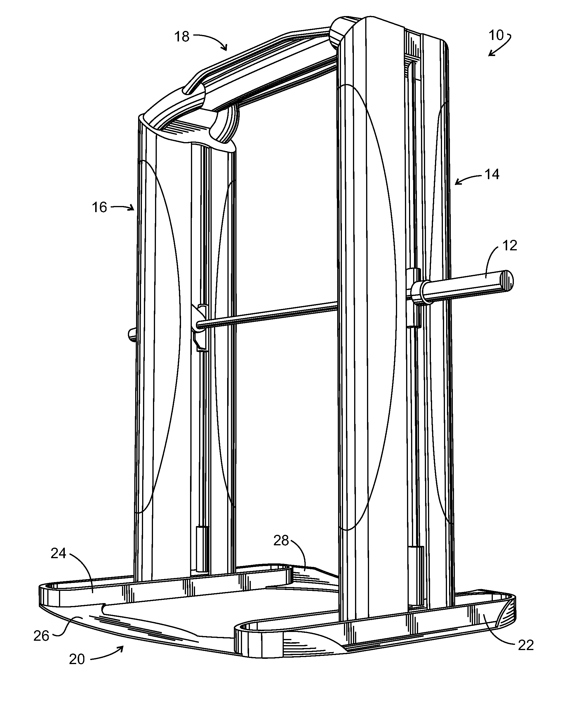
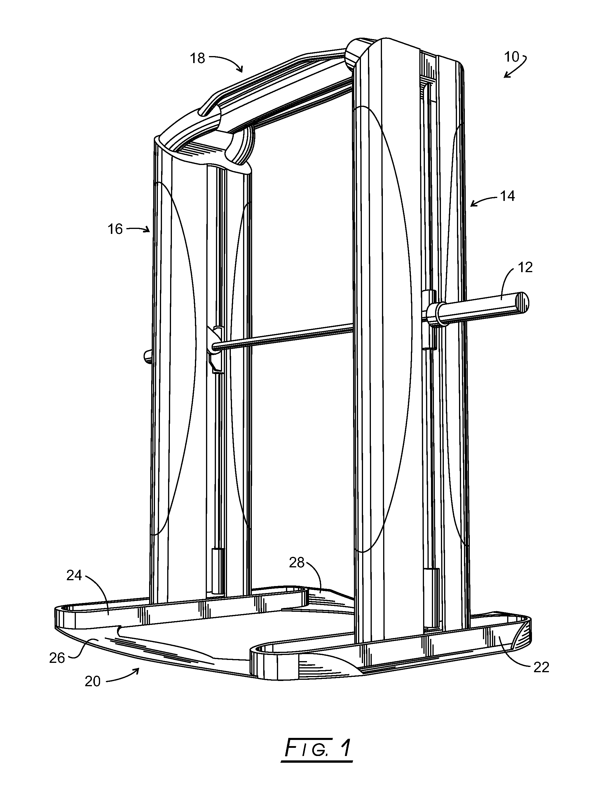
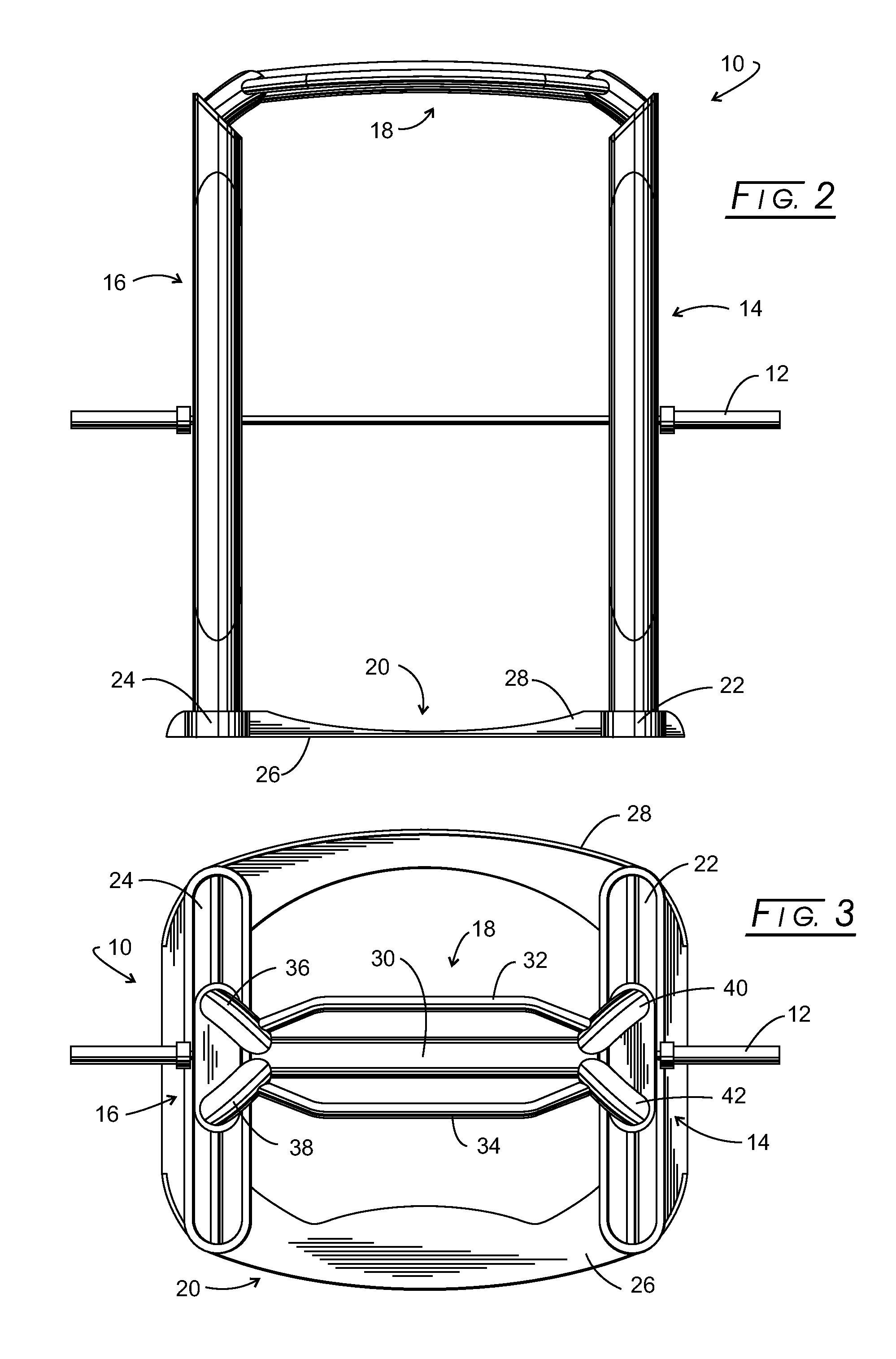
[0020]Definitional terms appropriate for the present invention include:[0021]“weight lifting power cage” or “power cage” means a frame assembly retaining a weight bar, upon which free weights can be secured, such as are disclosed in U.S. Pat. Nos. 5,215,510, 5,669,859, and 7,374,516.[0022]“rack” means to place a weight bar, barbell, or other weight lifting assembly to a stationary or home position.[0023]“vertical” means both upwardly and downwardly in a generally vertical direction.[0024]“lateral” means side to side.[0025]“depthenally” means front to back, back to front, or forwardly and rearwardly.[0026]“weight bar” means a generally horizontal bar, often made of metal, upon which weights, often called “free weights”, can be secured for a weight lifter or lifter to perform a series of repetitive movements of the weight bar as part of an exercise program or regimen, most often associated with body builders.

[0027]Initially, the drawings primarily show a purchaser or user of the discl...


PUM


Abstract

A weight lifting power cage for use by a weight lifter includes a floor frame assembly including a pair of side floor frames, a front lateral floor frame member, and a rear lateral floor member. A carriage is carried by the side floor frames and is movable simultaneously vertically and front to back. The carriage retains a weight bar mount for retaining a weight bar spanning between each side frame. The weight bar is movable by the carriage vertically and front to back. The movable carriage also carries a pair of vertical weight rack bars. An engagement mechanism enables the weight lifter to rack the weight bar from a weight lifting position without stepping forward or backward.

Description

CROSS-REFERENCE TO RELATED APPLICATIONS[0001]NoneSTATEMENT REGARDING FEDERALLY SPONSORED RESEARCH[0002]Not applicable.BACKGROUND[0003]The present invention generally relates to weight lifting cages for free weights and more particularly to a weight lifting cage having a movable carriage with slave racking capability.[0004]Safety is always a concern to weight lifters, especially as the amount of weight approaches and passes the body weight of the weight lifter. Even lesser amounts of weight can be dangerous if the lifter loses control of the weight bar. For that reason, a spotter often is employed to assist the lifter should the amount of weight being lifted prove uncontrollable or should the lifter lose his / her balance while lifting weights. Often, however, a spotter is unavailable to the lifter and other safety means need to be employed.[0005]One such other safety means is a weight lifting apparatus, often referred to as a power rack or power cage, such as is described in U.S. Pat....

Claims


Application Information

Patent Timeline
Patent Type & Authority Applications(United States)
IPC IPC(8): A63B21/078
CPCA63B21/0611A63B21/075A63B2021/0786A63B2021/0614A63B21/078A63B21/0626A63B21/0783A63B21/0628
Inventor LUNDQUIST, RANDAL L.
Owner RECREATION SUPPLY
Why Eureka
Try Eureka