Imaging system with disposable part

a technology of a disposable part and an imaging system, which is applied in the field of imaging systems with disposable parts, can solve the problems of unknowing people's mistaken sterilization of disposable parts, unfavorable system operation, and high cost of endoscopes, and achieves a high degree of system security

Inactive Publication Date: 2012-05-24
AMBU AS
View PDF11 Cites 22 Cited by
  • Summary
  • Abstract
  • Description
  • Claims
  • Application Information

AI Technical Summary

Benefits of technology

[0011]It is a first aspect of the current invention to provide an imaging system as mentioned in the introductory paragraph which is better than the prior art imaging systems. In particular it is an aspect of the current invention to provide

Problems solved by technology

Endoscopes are usually complicated electro-mechanical devices which are quite expensive.
However, one of the main problems with using an imaging system with a disposable part is that there is a risk that an unknowing person could mistakenly sterilize a disposable part after it has been used and attempt to use it on a new patient.
The danger in this case is that since the disposable part

Method used


Image

  • Imaging system with disposable part
  • Imaging system with disposable part
  • Imaging system with disposable part

Examples


first embodiment

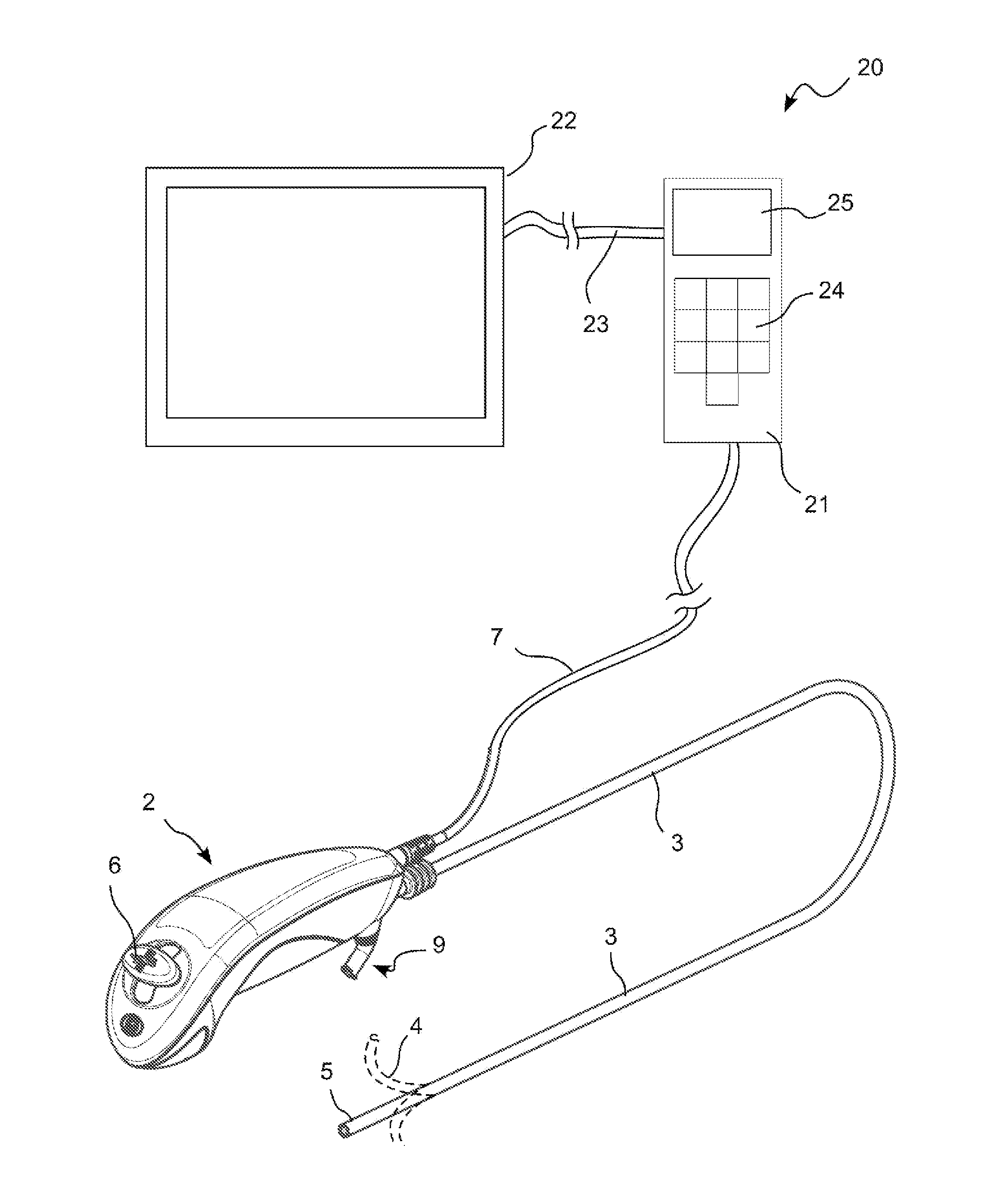
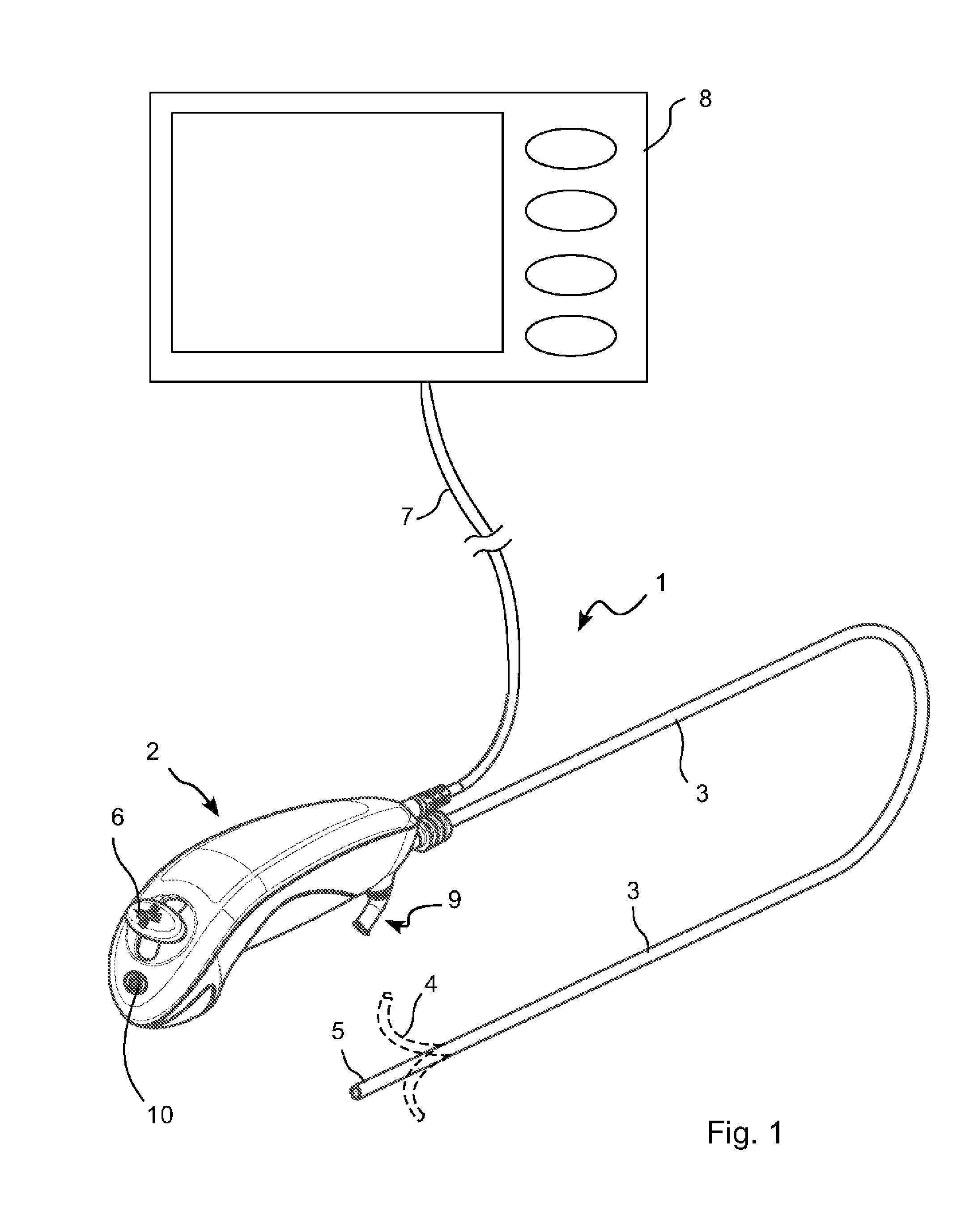
[0034]In a first embodiment, the disposable part comprises an electronic circuit.

[0035]Power to the electronic circuit is provided via the cable 7 from the control module 8. The electronic circuit could be the same electronic circuit which controls the camera device. The electronic circuit comprises a timing device which in this case is a counter (or timer) which counts the time which the disposable part is in use. The time which the disposable part is in use could be defined as the time in which the disposable part is actually transmitting an image signal to the control module or it could be defined as the time in which the control module is displaying an image from the disposable part. When the disposable part stops transmitting an image signal, or the control module stops displaying an image signal the counter will stop counting.

[0036]The counter value is stored on a non-volatile memory component in the electronic circuit. Since the memory component is non-volatile, the count val...

second embodiment

[0044]In an image system according to the current invention, the counter is not in the disposable part but is instead in the control module. A non-volatile memory component is however still present in the disposable part. The count value from the counter in the control module is constantly written to the non-volatile memory component in the disposable part. In this case, when the disposable part is disconnected from a control module and reconnected to another control module, the second control module can read the usage time from the disposable part and continue counting from the previous count stored in the disposable part. An advantage of this system over the previous embodiment is that the electronics on the disposable part can be made simpler. This will reduce the costs and complexity of the disposable part. This is especially true since in most cases, the camera device in the disposable part has control electronics which already comprise a non-volatile memory component. The soft...

third embodiment

[0049]A slight variant of this third embodiment is to use a super capacitor as the second counter. The super capacitor would be arranged to be charged up the first time it is connected. However, the super capacitor would also be arranged not to be further charged after the first full charge. In this way, the control module could be arranged to monitor the power level on the super capacitor. When the voltage of the super capacitor drops below a certain value, then the control module could stop displaying the image signal.

[0050]Another slight variant of this third embodiment is to use super capacitors for both first and second counters. The super capacitor which represents the first count value would be arranged to be prevented from discharging when the device is switched off or disconnected from the control module. This could be arranged by connecting the first super capacitor to an on / off switch which is controllable by the user. The first super capacitor could also be connected to ...


PUM


Abstract

An imaging system comprising a disposable part (1) comprising a camera device (5), said disposable part arranged to be suitable for allowing said camera device to be inserted into a body cavity, a reusable control module (8) in communication with said disposable part, said reusable control module comprising a display which displays image signals from the camera device in the disposable part, a timing device which generates time of use data of the disposable part, said time of use data representing the amount of time which the disposable part is in use, and said imaging system being arranged to prevent use of the disposable part if the time of use of the disposable part reaches a predefined level. The disposable part further comprises a non-volatile memory component which stores time of use data generated by said timing device and in that said reusable control module is arranged to continuously monitor the time of use data stored in the non-volatile memory component of the disposable part and to stop displaying image signals from the camera in the disposable part when the time of use data stored in the non-volatile memory component reaches said predefined level. In this way an imaging system is provided which is able to prevent using a disposable part which has been used on one patient on another patient.

Description

[0001]The current invention relates to an imaging system comprising a disposable part with a camera device and a reusable control module comprising a display. The disposable part is arranged to be suitable for allowing the camera device to be inserted into a body cavity. The reusable control module is arranged to be in communication with the disposable part and is able to display the image signals from the camera device in the disposable part on the display. The system further comprises a timing device which generates time of use data of the disposable part, said time of use data representing the amount of time which the disposable part is in use. The imaging system is furthermore arranged to prevent use of the disposable part if the time of use of the disposable part reaches a predefined level. This ensures that the disposable part will not be reused for multiple patients. This also ensures that the lifetime of the disposable part is controlled. In this way, the device can be manuf...

Claims


Application Information

Patent Timeline
IPC IPC(8): A61B1/04
CPCA61B1/0002A61B1/00039A61B1/00055A61B2560/0276A61B1/00105A61B1/04A61B1/267A61B1/00062A61B1/00042
Inventor BORRYE, STEENBORRYE, MERETE LOUISE
Owner AMBU AS
Why Eureka
Try Eureka