Device for focusing a microscope objective on a sample

a technology for focusing microscopes and samples, applied in the field of devices for focusing microscope objectives on samples, can solve the problems of affecting the focusing accuracy, affecting the accuracy of focusing, and unable to change the microscope objective easily, and achieve the effect of accurate focusing on samples and high spatial resolution

Inactive Publication Date: 2012-05-31
LEICA MICROSYSTEMS CMS GMBH
View PDF1 Cites 4 Cited by
  • Summary
  • Abstract
  • Description
  • Claims
  • Application Information

AI Technical Summary

Benefits of technology

[0013]It is an object of the present invention to provide a device that allows a microscope objective to be accurately focused on a sample with a high spatial resolution.

Problems solved by technology

However, this has the disadvantage that easy changing of microscope objectives is no longer possible.
Moreover, manipulation of the sample has a direct effect on the focusing unit, which may impair the focusing accuracy.
However, providing the clamping device makes this a relatively complex design.
The double parallel spring element acts on the end of the microscope objective that faces away from the sample, as a result of which the opposite free end of the microscope objective facing the sample may tilt to a not negligible degree, leading to unwanted image offset and a correspondingly reduced spatial resolution.

Method used


Image

  • Device for focusing a microscope objective on a sample
  • Device for focusing a microscope objective on a sample

Examples


Embodiment Construction

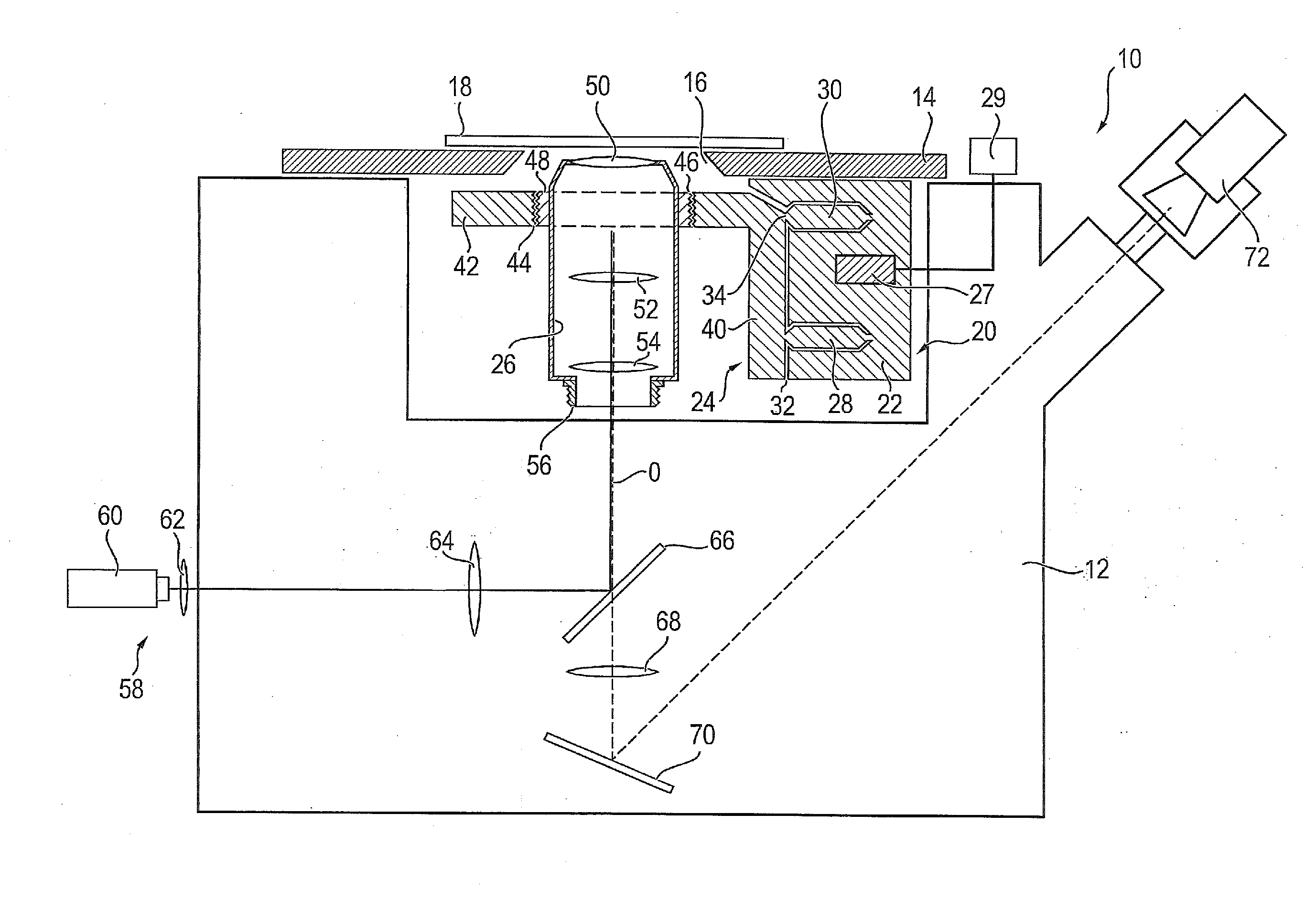
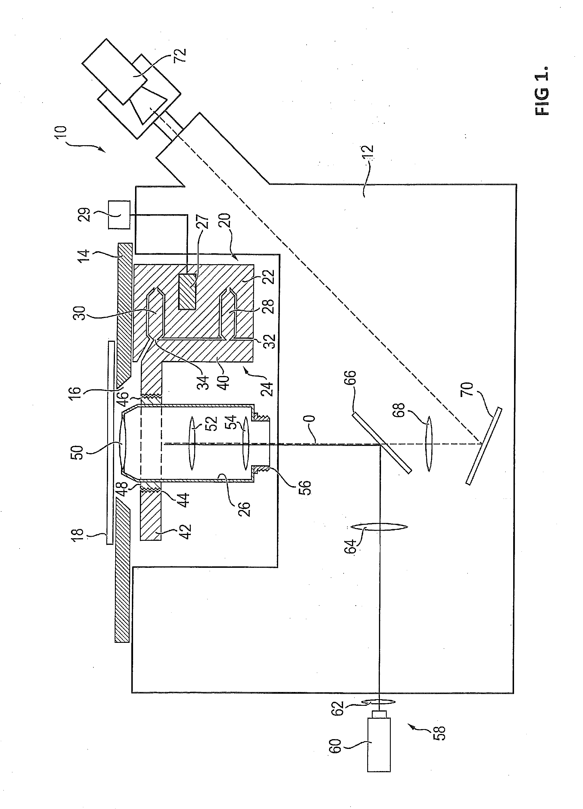
[0015]Thus, in contrast to the conventional systems where the microscope objective is held at the rear end; i.e., the end facing away from the sample (and usually by the thread provided at that end), it is a feature of the present invention that the microscope objective is held at a front portion facing the sample, which is where the so-called front lens is located. This is because it has been found that stabilizing the objective at its front end, as proposed by the present invention, has advantages over the conventional method of stabilizing it at its rear end when it comes to achieving the highest possible level of lateral resolution.

[0016]In a microscope objective, there is always a tilt-tolerant plane perpendicular to the optical axis, in which tilting of the microscope objective perpendicular to the optical axis does, at least in a first approximation, not result in image offset. This plane coincides with the first principal plane of the objective optical system. The exact posi...


PUM


Abstract

A device for focusing a microscope objective on a sample accurately with a high spatial resolution. The device has a positioning unit having a main body, an objective holder movably supported on the main body and adapted to hold the microscope objective, and an actuator for moving the objective holder along the optical axis of the microscope objective. The objective holder holds the microscope objective only at a front portion of the microscope objective facing the sample. The positioning unit includes one or more lever arms, each of which coupled at its one end via a first flexure bearing to the main body and at its other end via a second flexure bearing to the objective holder. The main body of the positioning unit is attached to a stage that carries the sample.

Description

CROSS-REFERENCE TO RELATED APPLICATION[0001]This application claims the priority of the German patent application DE 102010060841.6 having a filing date of Nov. 26, 2010. The entire content of this prior German patent application 102010060841.6 is herewith incorporated by reference.BACKGROUND OF THE INVENTION[0002]The present invention relates to a device for focusing a microscope objective on a sample, the device including a positioning unit having a main body, an objective holder movably supported on the main body and adapted to hold the microscope objective, and an actuator for moving the objective holder along the optical axis of the microscope objective.[0003]In high-resolution light microscopy, it is particularly important that the microscope objective be held in a stable and precise position in the imaging beam path. For example, the spatial resolutions to be achieved in modern light microscopic methods are desired to be below 50 nm in a lateral direction; i.e., perpendicular...

Claims


Application Information

Patent Timeline
Patent Type & Authority Applications(United States)
IPC IPC(8): G02B21/02
CPCG02B21/26G02B21/241
Inventor GANSER, MICHAEL
Owner LEICA MICROSYSTEMS CMS GMBH
Why Eureka
Try Eureka