Nuclear-power-plant soundness evaluation system

a nuclear power plant and soundness evaluation technology, applied in the direction of nuclear elements, instruments, greenhouse gas reduction, etc., can solve the problems of stress corrosion cracking (scc) of metallic materials used in structures and pipes, and achieve the effect of improving soundness evaluation accuracy

Inactive Publication Date: 2012-05-31
MITSUBISHI HEAVY IND LTD
View PDF2 Cites 8 Cited by
  • Summary
  • Abstract
  • Description
  • Claims
  • Application Information

AI Technical Summary

Benefits of technology

[0017]The present invention has advantages in that the soundness evaluation accuracy is improved and an appropriate maintenance measure can be provided on the basis of the evaluation result.

Problems solved by technology

In recent years, in nuclear power plants, stress corrosion cracking (SCC) of metallic materials used in structures and pipes has become a problem.

Method used


Image

  • Nuclear-power-plant soundness evaluation system
  • Nuclear-power-plant soundness evaluation system
  • Nuclear-power-plant soundness evaluation system

Examples


first embodiment

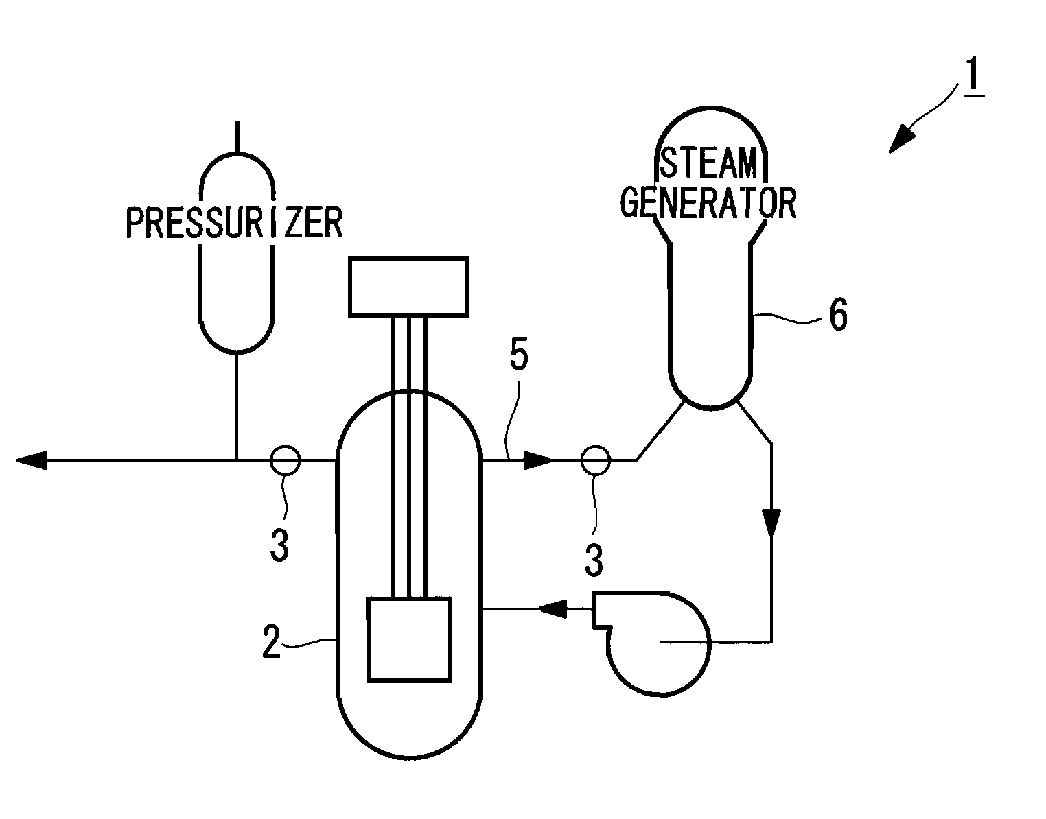
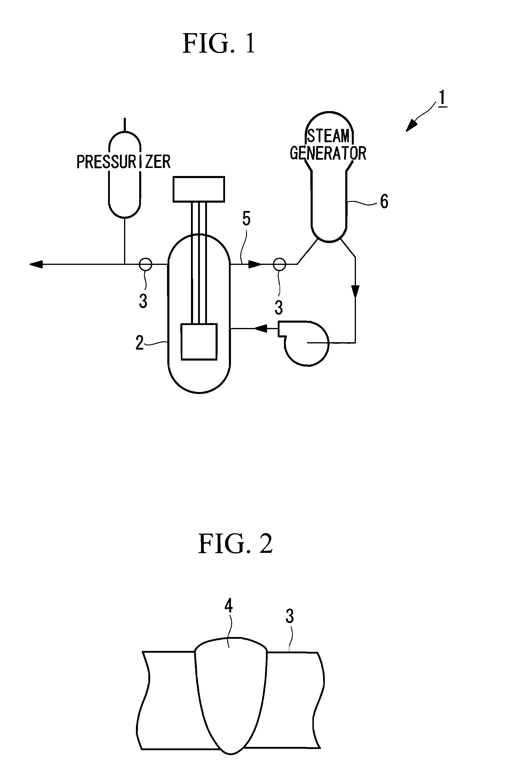
[0032]A nuclear-power-plant soundness evaluation system (hereinbelow simply, a “soundness evaluation system”) according to a first embodiment of the present invention will be described below with reference to the drawings. In this embodiment, an example case where the soundness of a primary refrigerant pipe 3 of a reactor vessel 2 in a nuclear power plant 1, as shown in FIG. 1, is evaluated will be described. More specifically, an example case where the soundness of a butt-welded portion 4 in the primary refrigerant pipe 3, as shown in FIG. 2, is evaluated will be described. Note that, in FIG. 1, high-temperature, high-pressure water 5 supplied from the reactor vessel 2 flows through the primary refrigerant pipe 3 into a steam generator 6.

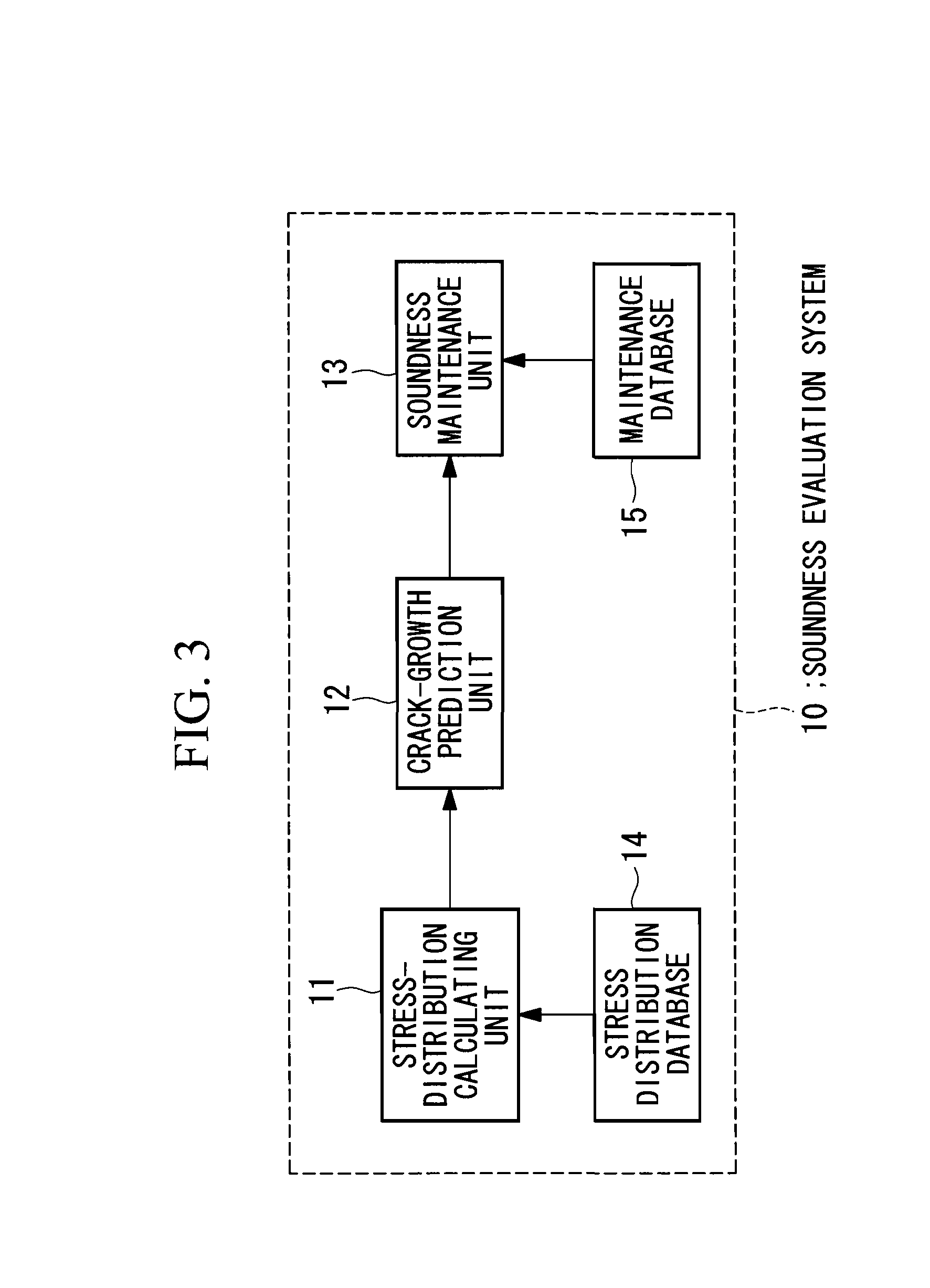
[0033]FIG. 3 is a schematic diagram showing the configuration of a soundness evaluation system 10 according to this embodiment. As shown in FIG. 3, the soundness evaluation system 10 mainly includes a stress-distribution calculating unit 11, a crac...

second embodiment

[0065]Next, a nuclear-power-plant soundness evaluation system according to a second embodiment of the present invention will be described below with reference to the drawings.

[0066]Calculation of the residual stress distribution in, for example, the butt-welded portion 4 described as an example in the first embodiment is not so troublesome because the shape thereof is not so complicated. However, calculation of the residual stress distribution in a nuclear power plant at each time for each part requires great effort and time because a large number of parts with complicated shapes are used in the plant. For instance, core instrumentation pipes are one example. FIG. 11 is a schematic view of the core instrumentation pipes supported by a lower head, viewed from the bottom of a vessel in a reactor, and FIG. 12 is a schematic cross-sectional view showing the core instrumentation pipes welded to the reactor bottom.

[0067]As shown in FIG. 11, the lower head of the reactor vessel supports a ...


PUM

PropertyMeasurementUnit
stress-aaaaaaaaaa
residual stress distributionaaaaaaaaaa
stress distributionaaaaaaaaaa

Abstract

A nuclear-power-plant soundness evaluation system includes a stress-distribution calculating unit that outputs a stress distribution and an identified crack generating part; a crack-growth prediction unit that predicts how the crack will grow from the crack generating part; and a soundness maintenance unit that has a maintenance database in which crack-growth prediction results and maintenance measures are associated and reads out from the maintenance database a maintenance measure corresponding to the crack-growth prediction result and presents the read-out maintenance information to a user.

Description

TECHNICAL FIELD[0001]The present invention relates to soundness evaluation in nuclear power plants.BACKGROUND ART[0002]In recent years, in nuclear power plants, stress corrosion cracking (SCC) of metallic materials used in structures and pipes has become a problem. Stress corrosion cracking is a fracture phenomenon that occurs when corrosion and tensile stress simultaneously act on metallic materials. The larger the stress, the more quickly the event may become evident.[0003]There is a known method for evaluating stress corrosion cracking in the related art in which the susceptibility to stress corrosion cracking and lifetime are evaluated on the basis of the hardness of a structural member (for example, see PTL 1). In this method, the correlation between the hardness of a structural member and the level of stress corrosion cracking is noted, and the susceptibility to stress corrosion cracking and the lifetime of the structural member are evaluated using this correlation.CITATION LI...

Claims


Application Information

Patent Timeline
Patent Type & Authority Applications(United States)
IPC IPC(8): G06F19/00G01L1/04G01L1/00
CPCG01M5/0033Y02E30/40G21D3/04G21C17/00Y02E30/00Y02E30/30G01N17/00G21D1/00
Inventor OGAWA, NAOKIKOBAYASHI, TAKAAKIMATSUBARA, NARIYASU
Owner MITSUBISHI HEAVY IND LTD
Why Eureka
Try Eureka