Hydraulic control device

a technology of hydraulic control device and engagement element, which is applied in the direction of non-mechanical actuated clutches, clutches, gearing elements, etc., can solve the problems of poor controllability of the output oil pressure for engaging the engagement element, and achieve the effect of improving controllability, simple structure and reducing the number of components

Active Publication Date: 2012-06-07
HONDA MOTOR CO LTD
View PDF2 Cites 17 Cited by
  • Summary
  • Abstract
  • Description
  • Claims
  • Application Information

AI Technical Summary

Benefits of technology

[0017]According to the third aspect of the present invention, it is possible to switch the gain characteristic of the linear solenoid valve which supplies the output oil pressure selectively to the two engagement elements having different necessary oil pressures according to the levels of the necessary oil pressures. Therefore, compared with the case where only one gain characteristic is used to cope with such situation, it is possible to ensur

Problems solved by technology

However, since the control range of electric current for regulating the necessary oil pressure to a low pressure is narrow,

Method used


Image

  • Hydraulic control device
  • Hydraulic control device
  • Hydraulic control device

Examples


first embodiment

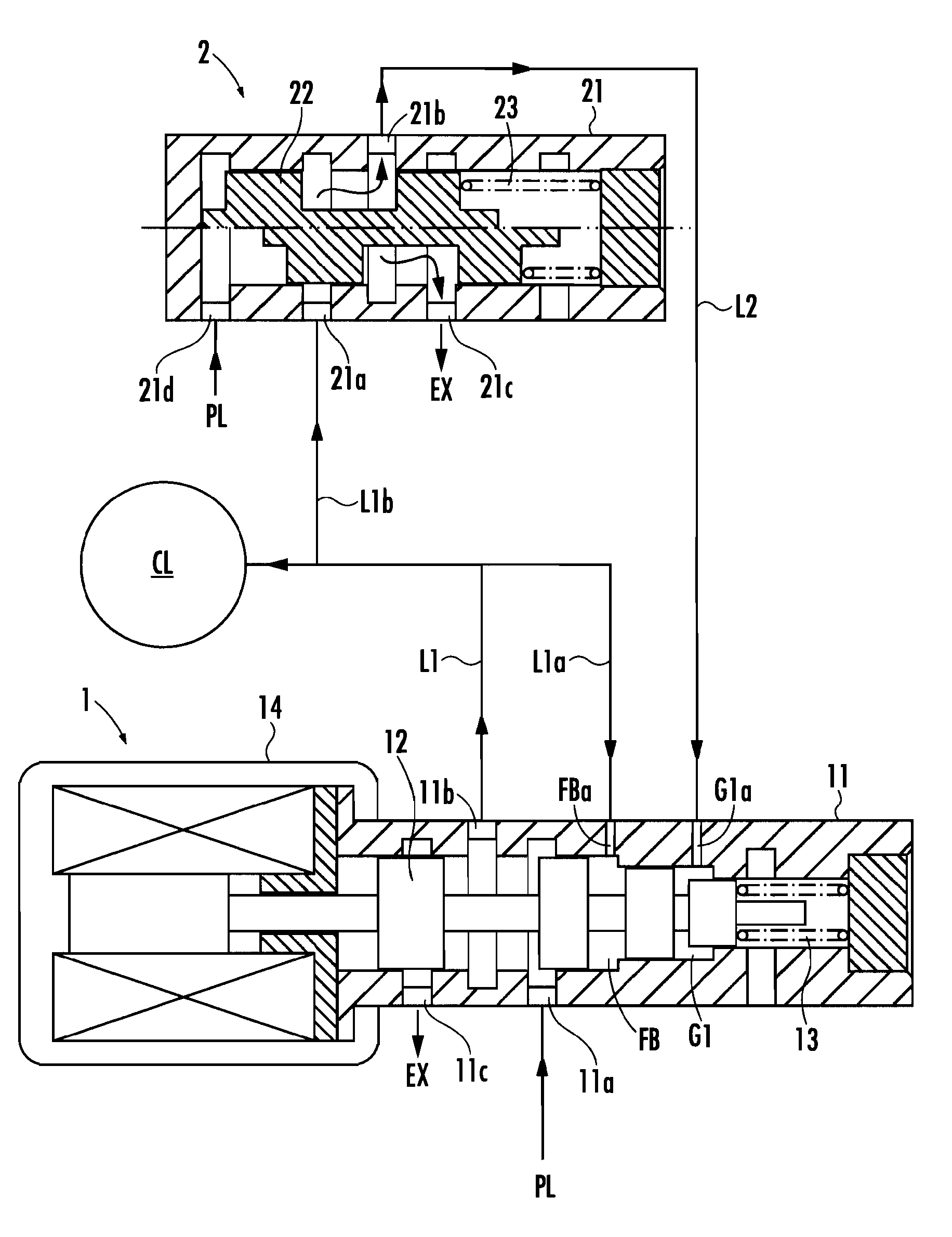
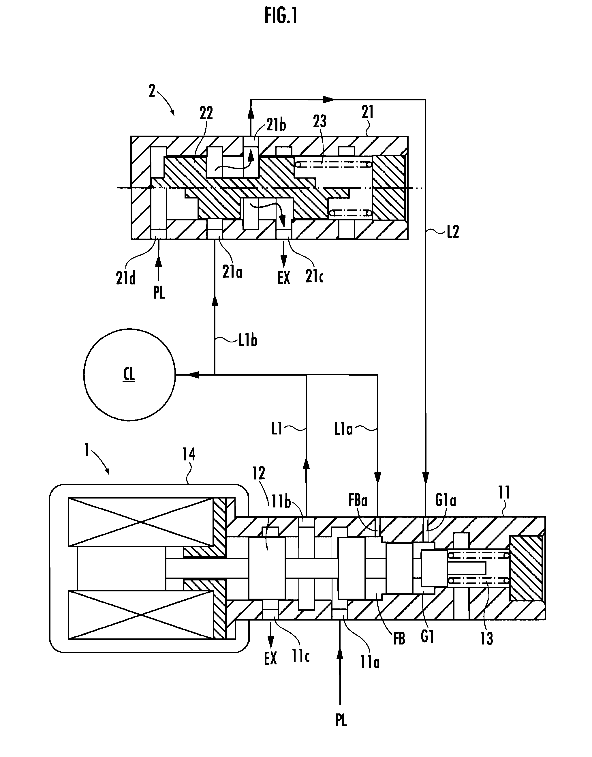
[0027]A first embodiment of the present invention will be described in detail with reference to FIG. 1 and FIG. 2. A hydraulic control device of the first embodiment is provided with a linear solenoid valve 1 configured to regulate a line pressure PL and supply it to a wet multi-plate clutch CL equivalent to an engagement element of an automatic transmission, a shift valve 2 supplied with an output oil pressure from the linear solenoid valve 1, and a transmission control unit TCU (not shown) equivalent to a controller configured to control the linear solenoid valve 1 and the shift valve 2.

[0028]The linear solenoid valve 1 is a normally close typed valve which is closed in a state where no electric current is applied (non-conducting state), and is composed of a sleeve 11, a spool 12 slidably inserted in the sleeve 11, a spring 13 biasing the spool 12 toward the left side of FIG. 1, and a linear solenoid 14 capable of biasing the spool 12 toward the right side of FIG. 1 against a bias...

second embodiment

[0049]A second embodiment of the present invention will be described in detail with reference to FIG. 4 through FIG. 6. Similar to the first embodiment, the hydraulic control device of the second embodiment is provided with the linear solenoid valve 1 configured to regulate the line pressure PL and supply it to the wet multi-plate clutch CL, and the shift valve 2.

[0050]In the second embodiment, a circular second gain switching chamber G2 is defined in the linear solenoid valve 1 by the sleeve 11 and the spool 12 at a position right to the feedback chamber FB. Similar to the first gain switching chamber G1, the second gain switching chamber G2 is also configured in such a way that the surface area of the spool 12 constituting the end surface toward the linear solenoid 14 (left side) is greater than the surface area of the spool 12 constituting the end surface toward the spring 13 (right side).

[0051]The sleeve 11 is drilled with a second gain switching port G2a in communication with t...

third embodiment

[0065]A third embodiment of the present invention will be described in detail with reference to FIG. 7 and FIG. 8. The hydraulic control device of the third embodiment is provided with the linear solenoid valve 1 configured to regulate the line pressure PL for outputting, and the shift valve 2 to which the output oil pressure of the linear solenoid valve 1 is supplied.

[0066]The linear solenoid valve 1 in the third embodiment is identical to that in the first embodiment.

[0067]The shift valve 2 in the third embodiment selectively supplies the output oil pressure from the linear solenoid valve 1 to an actuation oil pressure chamber 31 serving as a driving source for driving a shift fork 3 which in turn drives a sleeve disposed in the wet multi-plate clutch CL or an intermeshing mechanism (not shown. It is acceptable that the intermeshing mechanism has a synchromesh function.).

[0068]The shift valve 2 of the third embodiment will be described in detail hereinafter. The sleeve 2 of the sh...


PUM


Abstract

A hydraulic control device is provided with a linear solenoid valve, a shift valve, and a controller. The linear solenoid valve has a gain switching chamber which produces a biasing force in a direction to close the linear solenoid valve to switch the gain characteristic of the linear solenoid valve when oil pressure is supplied to the gain switching chamber. The shift valve is configured to be switchable between a supply state in which the output oil pressure from the linear solenoid valve is supplied to the gain switching chamber and a blocked state in which the supply of the output oil pressure is blocked. The controller brings the shift valve into the supply state when a necessary oil pressure of an engagement element is high and into the blocked state when the necessary oil pressure of the engagement element is low.

Description

BACKGROUND OF THE INVENTION[0001]1. Field of the Invention[0002]The present invention relates to a hydraulic control device for an automatic transmission.[0003]2. Related Background Art[0004]Hitherto, there has been known a hydraulic control device for an automatic transmission provided with a regulator valve which is configured to regulate a line pressure to be supplied freely to an engagement element and a linear solenoid valve which is configured to regulate a line pressure for adjusting an opening degree of the regulator valve and supply it to one end of the regulator valve (for example, refer to Japanese Patent Laid-open No. 2005-90665). Moreover, there has been known as well a device which is configured to supply an output oil pressure from the linear solenoid valve directly to the engagement element.[0005]In the conventional hydraulic control device, in coping with plural oil pressures, the maximum output oil pressure from the linear solenoid valve is preliminarily set at the...

Claims


Application Information

Patent Timeline
IPC IPC(8): F16D25/12
CPCF16H61/0206F16H61/0251F16H2061/0253Y10T477/6936F16D48/02F16D2048/0209F16D2048/0281F16H2061/0209
Inventor YAGI, NORIYUKI
Owner HONDA MOTOR CO LTD
Why Eureka
Try Eureka