Solder feeder, printer, and printing method

a feeder and printer technology, applied in the field of printing technology, can solve the problems of reducing the versatility of the device, dripping solder might adhere to an inappropriate section of the substrate, cycle loss, etc., and achieve the effect of preventing the occurrence of cycle loss and enhancing versatility

Active Publication Date: 2012-06-07
YAMAHA MOTOR CO LTD
View PDF14 Cites 31 Cited by
  • Summary
  • Abstract
  • Description
  • Claims
  • Application Information

AI Technical Summary

Benefits of technology

[0011]According to the present inventions (the solder feeder, the printer, and the printing method) configured as above, the forward print process and the backward print process are performed by a single squeegee, and the squeegee is switched and moved at a timing of switching between the forward print process and the backward print process. When the squeegee passes through the solder pool at the downstream in the moving direction prior to the switching in the course of switching from any one of the forward print process and the backward print process to the other, the amount of solder in the solder pool is measured. Based on the measured amount of solder, it is determined as to whether replenishment of the solder is necessary or not. Thus, even if the solder adhered to the squeegee drips during the solder amount measurement, the drop of the solder adheres to a non-opening part of the mask. For this reason, the amount of solder in the solder pool can be measured without employing the operation sequence that causes cycle loss. Moreover, it is no longer necessary to cause the squeegee to overrun excessively at the non-opening part of the mask. Accordingly, the amount of solder in the solder pool can be measured in a short period of time during the solder printing processes regardless the masks having an opening part not only with a comparatively small region, but also with a comparatively large region. Judgment as to whether solder replenishment is required is determined based on the amount of solder that is measured as described above, and the solder pool is replenished with the solder as needed, whereby the solder pool is regulated.
[0012]As described above, according to the present invention, the amount of solder in the solder pool can be measured when the squeegee passes through the solder pool at the non-opening part of the mask at the time of switching. Therefore, the solder adhering to the squeegee during the measurement of the solder pool can be prevented from dripping on the opening part of the mask. Consequently, the amount of solder in the solder pool can be measured without employing the operation sequence causing cycle loss, whereby the occurrence of cycle loss can be prevented. Furthermore, the amount of solder in the solder pool can be measured during the operation of switching the position of the squeegee in relation to the solder pool, and the limit that is set on the size of the substrate in the prior art can be eliminated, enhancing the versatility. Based on the amount of solder measured as described above, the solder pool can be regulated by replenishing the solder pool with the solder as necessary.

Problems solved by technology

In this case, if the position of the substrate is not accurately positioned to the mask, the dripping solder might adhere to an inappropriate section of the substrate (a section where the solder is not supposed to be applied).
However, employing such an operation sequence causes delay in start of the subsequent printing due to the solder detection and replenishment, resulting in cycle loss.
In other words, a limit needs to be set on the size of the substrate, causing a reduction in the versatility of the device.

Method used


Image

  • Solder feeder, printer, and printing method
  • Solder feeder, printer, and printing method
  • Solder feeder, printer, and printing method

Examples


first embodiment

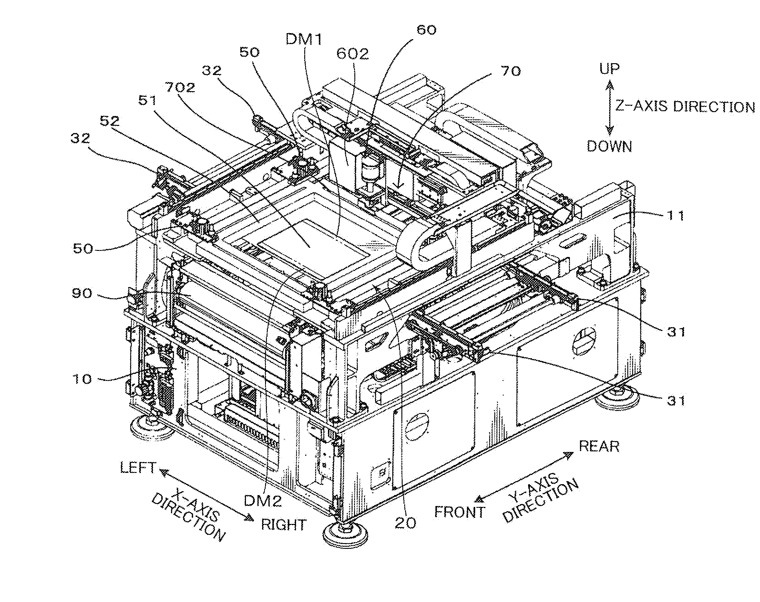
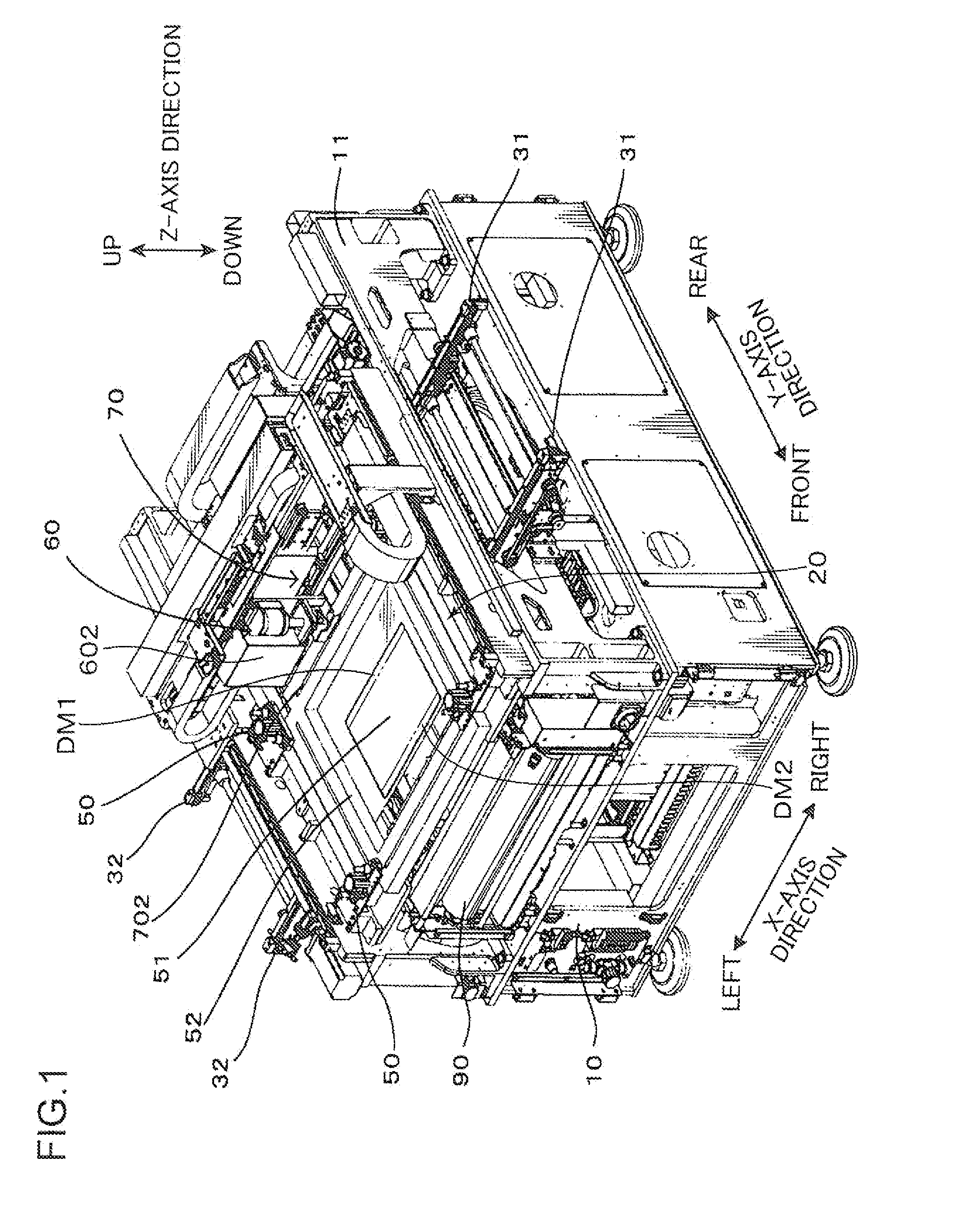
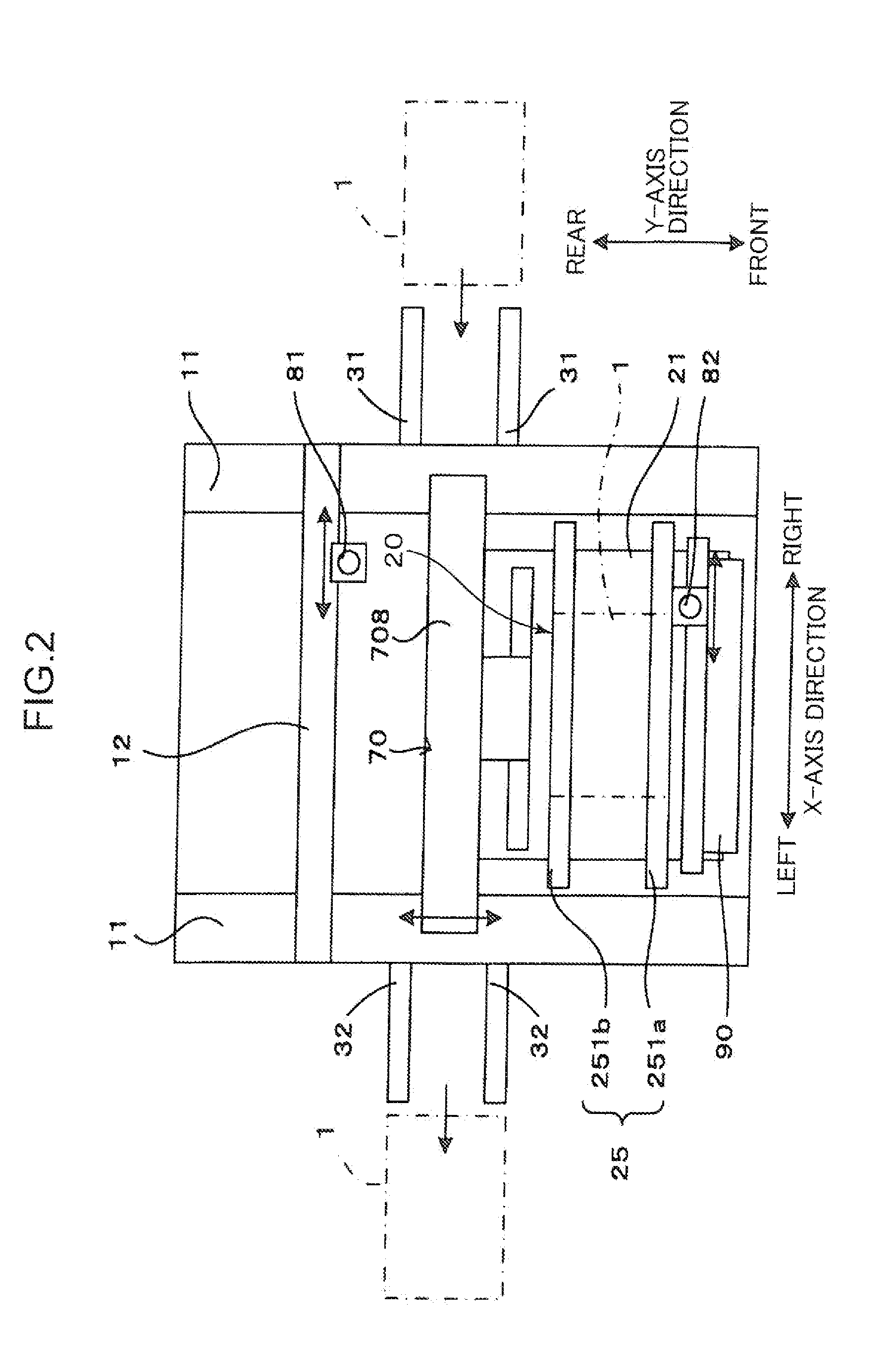
[0024]As shown in FIGS. 1 to 3, a printer according to the present invention has a base 10 in substantially a quadrangle shape in a planar view, and a substrate delivery mechanism 20 that freely moves back and forth on the base 10 with respect to the printer. The substrate delivery mechanism 20 has a conveyor unit 25 that has a pair of main conveyors 251a, 251b capable of driving a substrate 1 on the base 10 side to side with respect to the printer. The printer also has carrying-in conveyors 31, 31 that are equipped with a right side of the base 10 and carry the unprocessed substrate 1 into the conveyor unit 25, carrying-out conveyors 32, 32 that are equipped with a left side of the base 10 and carry the processed substrate 1 out of the conveyor unit 25, and a control unit 40 that controls the entire printer (see FIG. 4). The substrate delivery mechanism 20, carrying-in conveyors 31, 31 and carrying-out conveyors 32, 32 are controlled by a substrate delivery mechanism controller 43 ...

fourth embodiment

[0074]As shown in “the fourth embodiment” column in FIG. 10, the “solder amount measuring” process and the “solder replenishing” process may be executed each time when printing is executed on a predetermined number of substrates 1. As a result, the time require for the “solder amount measuring” process or the “solder replenishing” process can be saved, improving the print efficiency.

[0075]In addition, according to the first embodiment, the amount of solder in the solder pool SP is measured by the single sensor SC that is attached to the side surface of the sub frame 722, which is located on the side opposite to the gear box 732, as shown in FIG. 5. However, the type and the number of sensors, as well as the place for disposing the sensor, are not limited. As shown in FIG. 11, for example, sensors SC1, SC2 may be attached to the rear side and the front side of the print head 704 in the Y-axis direction, and output signals from these sensors SC1, SC2 may be used separately in accordan...


PUM

PropertyMeasurementUnit
widthaaaaaaaaaa
distanceaaaaaaaaaa
sizeaaaaaaaaaa

Abstract

Disclosed is a print technology in which a solder pool staying on the surface of a mask is driven by means of a squeegee, and solder is applied onto a substrate onto which the lower surface of a mask is placed. A forward print process where solder is applied by driving a squeegee in a predetermined forward direction relative to a mask, and a backward print process where the solder is applied by driving the squeegee in a returning direction opposite to the forward direction are switched alternately. When the squeegee passes through the solder pool on the downstream side in a moving direction before switching in the course of switching from any one of the forward and backward print processes to the other one of these processes, the amount of solder in the solder pool is measured. Based on the amount of solder thus measured, the necessity of replenishing solder is determined The solder pool is supplemented with solder, based on the result of the decision on whether solder replenishment is required.

Description

TECHNICAL FIELD [0001]The present invention relates to a print technology for applying solder onto a substrate through a mask of which lower surface is put on the top of the substrate, by pressing a solder pool staying on the surface of the mask using a squeegee while sliding the squeegee on the surface of the mask in order to apply solder, and, more particularly, relates to a technology for replenishing the solder pool with solder.BACKGROUND ART [0002]There has been generally known a conventional printer in which a mask is put on the top of a substrate. A solder pool staying on the surface of the mask is pressed and moved on the surface of the mask by a squeegee, whereby solder is applied (printed) onto a predetermined position on the substrate through an opening part formed on the mask. In this printer, the solder pool is formed by accumulating solder that is substantially greater in amount than solder used on a single substrate. When printing using this solder pool, the solder is...

Claims


Application Information

Patent Timeline
Patent Type & Authority Applications(United States)
IPC IPC(8): B23K3/06B23K1/00
CPCB41F15/0881B41F15/26B41F15/36B41F15/423B41F15/46B41F33/02H05K2203/163B41P2215/114B41P2215/50H05K3/1233H05K3/3484H05K2203/1492B41P2215/112H05K3/3485B41F15/08B41F15/40B41F33/14H05K3/34
Inventor SUMIOKA, KOUICHI
Owner YAMAHA MOTOR CO LTD
Why Eureka
Try Eureka