Device and method for the transmission and reception of high fidelity audio using a single wire

Inactive Publication Date: 2012-06-07
DIALOG SEMICONDUCTOR
View PDF1 Cites 60 Cited by
  • Summary
  • Abstract
  • Description
  • Claims
  • Application Information

AI Technical Summary

Problems solved by technology

This level of fidelity is particularly challenging in situations where the audio signal must be transmitted between two audio integrated circuits (ICs) resident on a compact and densely populated printed circuit board (PCB).
Under such conditions, a transmitted HIFI audio signal is subject to substantial noise and interference.
Further, tight PCB layouts make it very difficult to isolation the HIFI signal from interference using spacing, routing, and grounding techniques.
However, single wire transmission is very susceptible to noise pickup and must be very well isolated from other PCB conductors.
The necessary isolation distances and grounding make single wire transmission of analog HIFI audio signals unsuitable for compact and densely populated PCBs.
However, differential signals require at least two wires and increase the area used.
However, a PWM signal is sensitive to mismatch in the rise and fall time constraints of its pulse.
In addition, if there is any jitter on this clock, then this jitter will adversely affect the quality of the sound reproduced.
However, I2S is not particularly useful for densely packed PCB application because the physical layer requires separate data, word clock, and bit clock

Method used


Image

  • Device and method for the transmission and reception of high fidelity audio using a single wire
  • Device and method for the transmission and reception of high fidelity audio using a single wire
  • Device and method for the transmission and reception of high fidelity audio using a single wire

Examples


Embodiment Construction

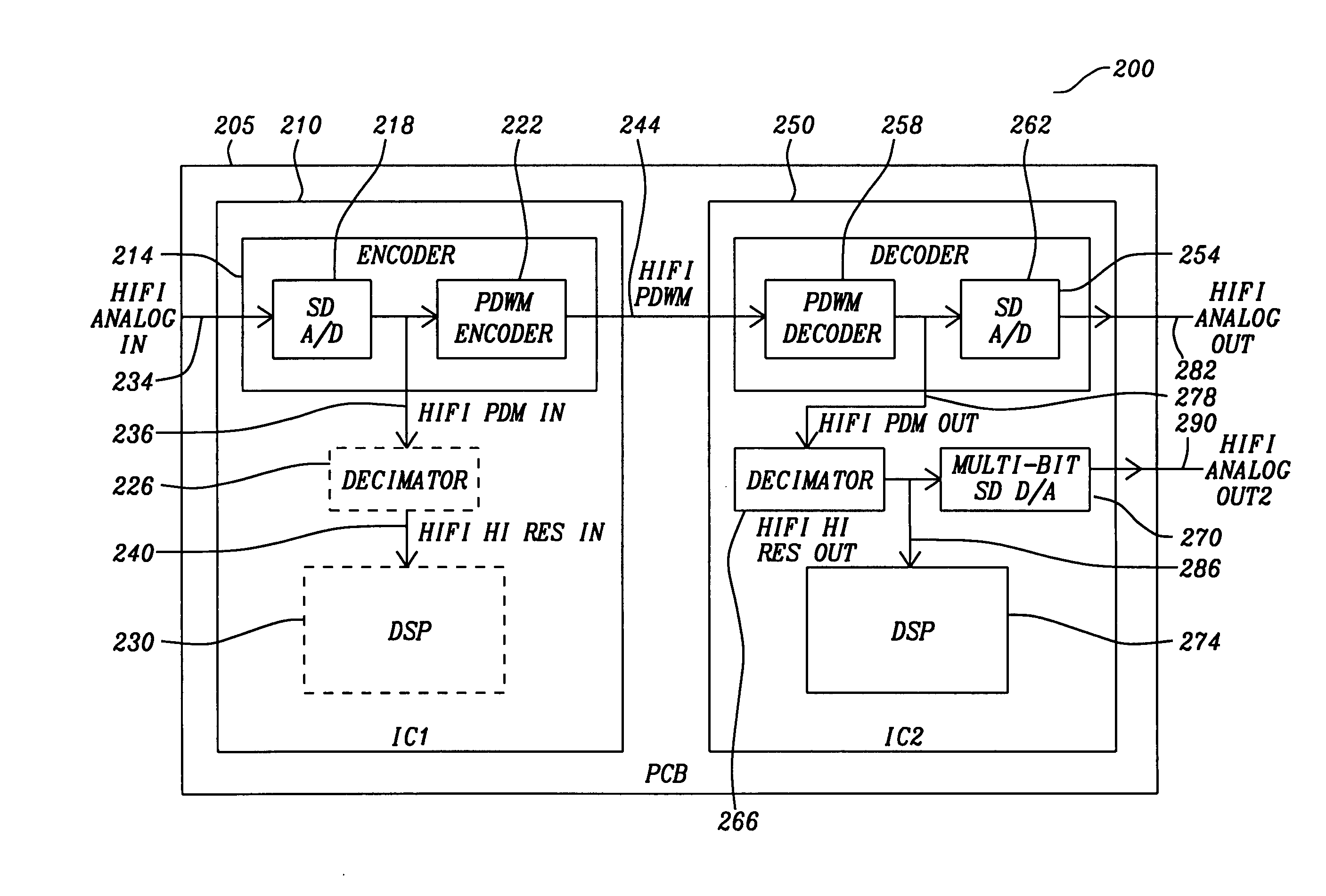
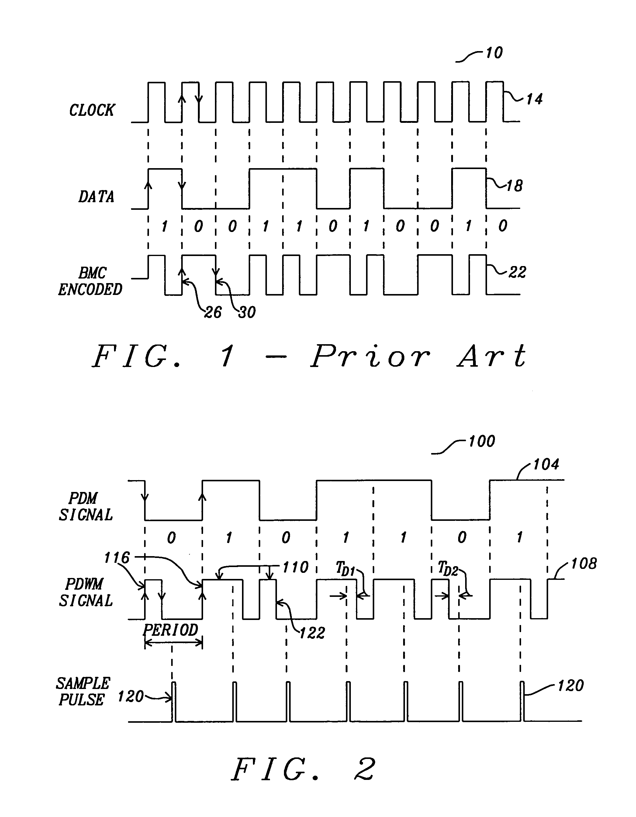
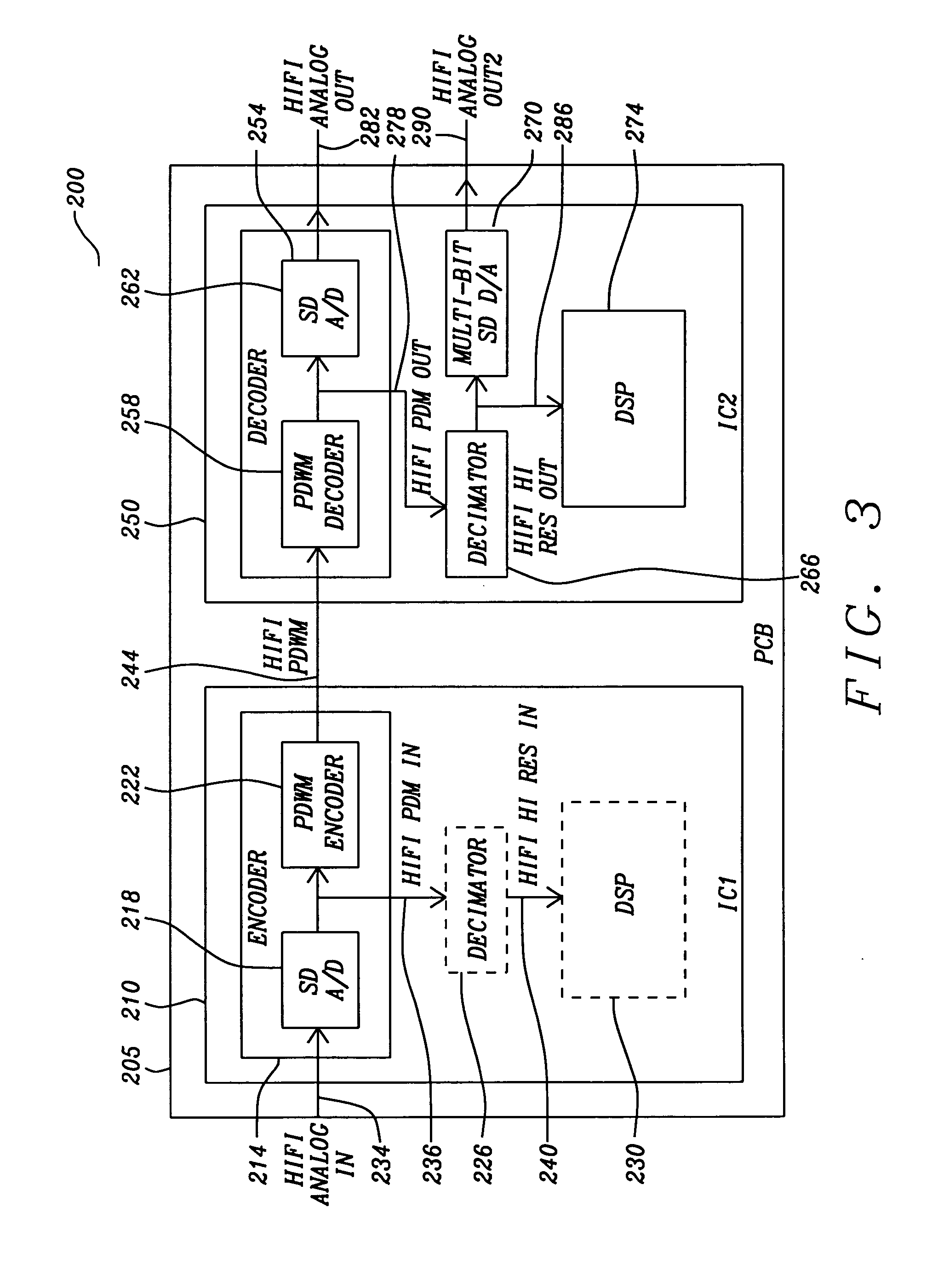
[0019]A novel method and device provides improved performance in the transmissions and reception of analog signals and, more particularly, high fidelity audio signal. The method and device provide these improvements by, among other things, encoding an analog signal as a pulse density width modulated signal that is more robust for transmission, reception, and recovery. In an exemplary embodiment of the present invention, a method for encoding an analog signal receives an analog signal, converts the analog signal into a pulse density modulated signal by sigma-delta, analog-to-digital conversion, and encodes the pulse density modulated signal into a pulse density width modulated signal. A plurality of discrete pulse widths corresponds to a plurality of pulse density modulated signal bit levels. A leading edge of each pulse bounds each pulse period.

[0020]In another exemplary embodiment of the present invention, a method for decoding a pulse density modulated signal from a pulse density ...


PUM


Abstract

An audio device (200) includes a first and second ICs (210) and (250) and a substrate (205). The first IC includes a sigma-delta, A/D converter (218) operable to convert an analog signal (234) into a pulse density modulated signal (236). A pulse density width modulator encoder (222) is operable to encode the PDM signal into a PDWM signal (244). The PDWM has short and long pulse widths defining first and second bit levels. The leading edges of each pulse bounds each pulse period. The second IC (250) includes a means (254) to receive the PDWM signal, an edge detector (304) operable to detect the leading pulse edges of the PDWM signal, a time-averaging circuit (308) operable to calculate each pulse period from the leading pulse edges and to generate a sample pulse (120) at near the midpoint of each pulse period, and a latch (312) operable to sample and hold the PDWM signal at the sample pulse to decode a PDM signal (278). The substrate is operable to support the first and second ICs and to conduct the PDWM signal between the first and second ICs.

Description

FIELD OF THE INVENTION[0001]The invention relates generally to audio devices and, more particularly, to encoding methods for transmitting and receiving high-fidelity audio signals between audio device circuits.BACKGROUND OF THE INVENTION[0002]The human ear is very sensitive to noise and particularly sensitive to distortion in audio signals. For example, to maintain auditory purity, a high fidelity (HIFI) audio signal must be transmitted, encoded, decoded, and reproduced with a very high dynamic range (100 to 120 dB) and carry very little distortion (−90 to −110 dB). This level of fidelity is particularly challenging in situations where the audio signal must be transmitted between two audio integrated circuits (ICs) resident on a compact and densely populated printed circuit board (PCB). Under such conditions, a transmitted HIFI audio signal is subject to substantial noise and interference. Further, tight PCB layouts make it very difficult to isolation the HIFI signal from interferen...

Claims


Application Information

Patent Timeline
IPC IPC(8): H03M3/00
CPCH03M5/08H03M5/14H03M3/458H03M3/50H04B14/026
Inventor LOEDA, SEBASTIANHAGUE, GARY
Owner DIALOG SEMICONDUCTOR
Why Eureka
Try Eureka