Dynamic Changeable Focus Contact And Intraocular Lens

a contact and focus technology, applied in the field of dynamic changeable focus contact and intraocular lens, can solve the problems of increased cost, increased difficulty in obtaining, and inconvenient use of intraocular lenses and contact lenses by presbyopes, and achieve the effect of reducing the overall size of the devi

Inactive Publication Date: 2012-06-07
HPO ASSETS
View PDF4 Cites 285 Cited by
  • Summary
  • Abstract
  • Description
  • Claims
  • Application Information

AI Technical Summary

Benefits of technology

[0061]Embodiments may provide a dynamic focusing lens. The dynamic focusing lens may comprise a contact lens or an intraocular lens that includes a dynamic optic and an electronic component. The dynamic optic may comprise a fluid lens. In some embodiments, the dynamic focusing lens may comprise a self-contained electronics module that may be inserted into (or otherwise be disposed within) the intraocular lens or a contact lens (or components thereof). The sealed self-contained electronics module may contain the dynamic optic (e.g. a dynamic lens) that may provide a changeable optical power to a portion of the intraocular lens or contact lens, such that when activated, a wearer of the dynamic focusing lens may be provided with a different optical power in comparison to when the dynamic optic is not activated. For instance, the dynamic optic may provide plus optical power corresponding to a wearer's near vision prescription when activated. The host lens—e.g. the contact lens or the intraocular lens—and / or the self-contained electronics module that may contain the dynamic focusing lens in some embodiments, may comprise other components that may be related to the operation of the dynamic optic, such as a power source, controller, sensors, etc. The components and / or the dynamic optic may be configured, in some embodiments, so as to reduce the overall size of the device such that it may be comfortably worn either as a contact lens or an intraocular lens. In some embodiments comprising a self-contained electronics module, the electronics module may be fabricated in a separate process from the other components of the dynamic focusing lens (e.g. in a separate process than the contact lens matrix) and may be inserted into, or otherwise disposed within, the host lens in a separate process. The self-contained electronics module may have a thickness that is less than approximately 125 microns in some embodiments, which may correspond to thickness that may be preferred such that the dynamic focusing lens may be comfortably worn by a wearer.

Problems solved by technology

This appears to be especially true in developed countries, where individuals may have better access to intraocular lenses and contact lenses (which may be more expensive, or more difficult to obtain in less developed countries).
Typically, intraocular lenses and contact lenses may not be comfortably used by presbyopes (i.e. individuals suffering from presbyopia), because, for instance, presbyopes typically require an added plus optical power (to correct for accommodation deficiency) only when viewing near objects, and may require a second optical power for intermediate or far distance viewing.
This may be distracting to a wearer and / or may impair the wearer's vision.

Method used


Image

  • Dynamic Changeable Focus Contact And Intraocular Lens
  • Dynamic Changeable Focus Contact And Intraocular Lens
  • Dynamic Changeable Focus Contact And Intraocular Lens

Examples


Embodiment Construction

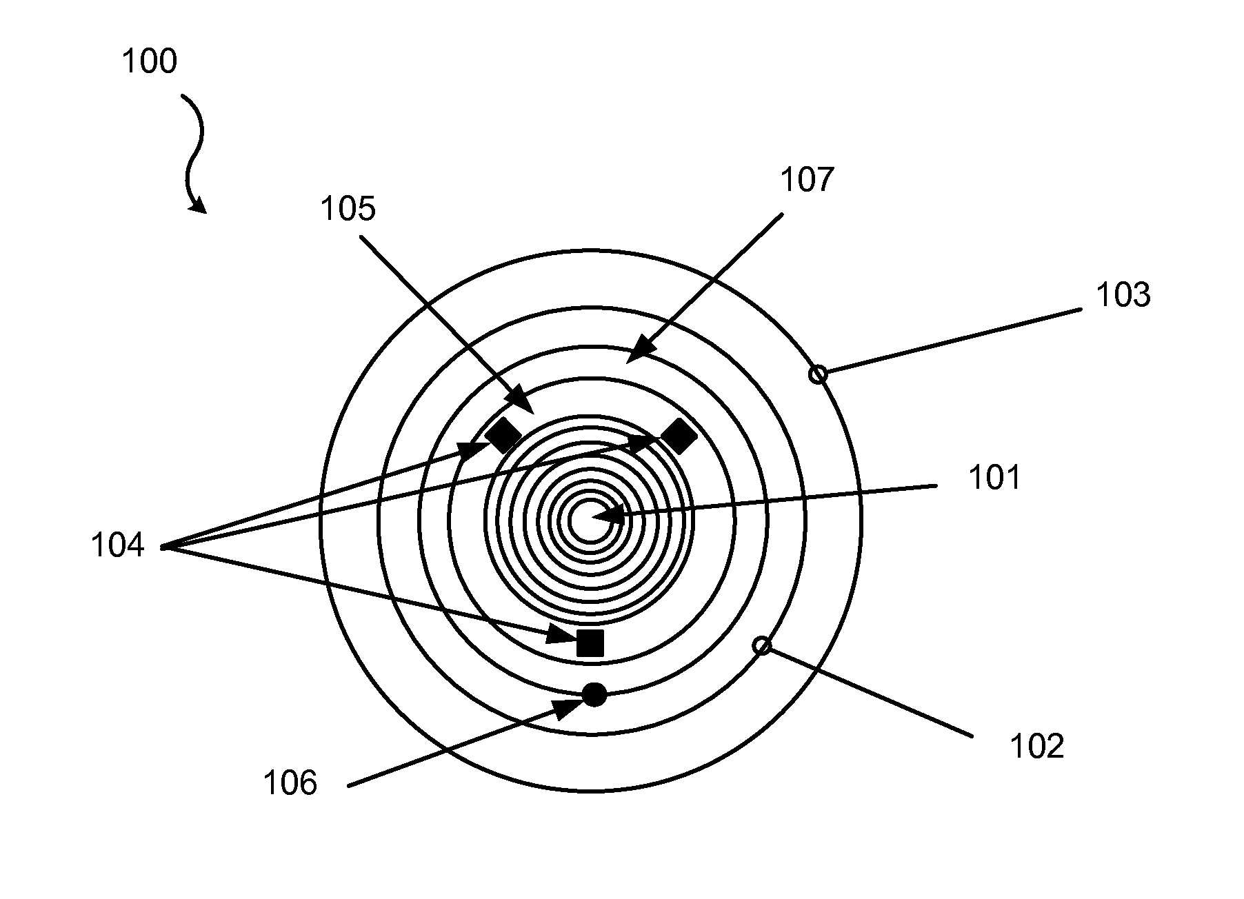
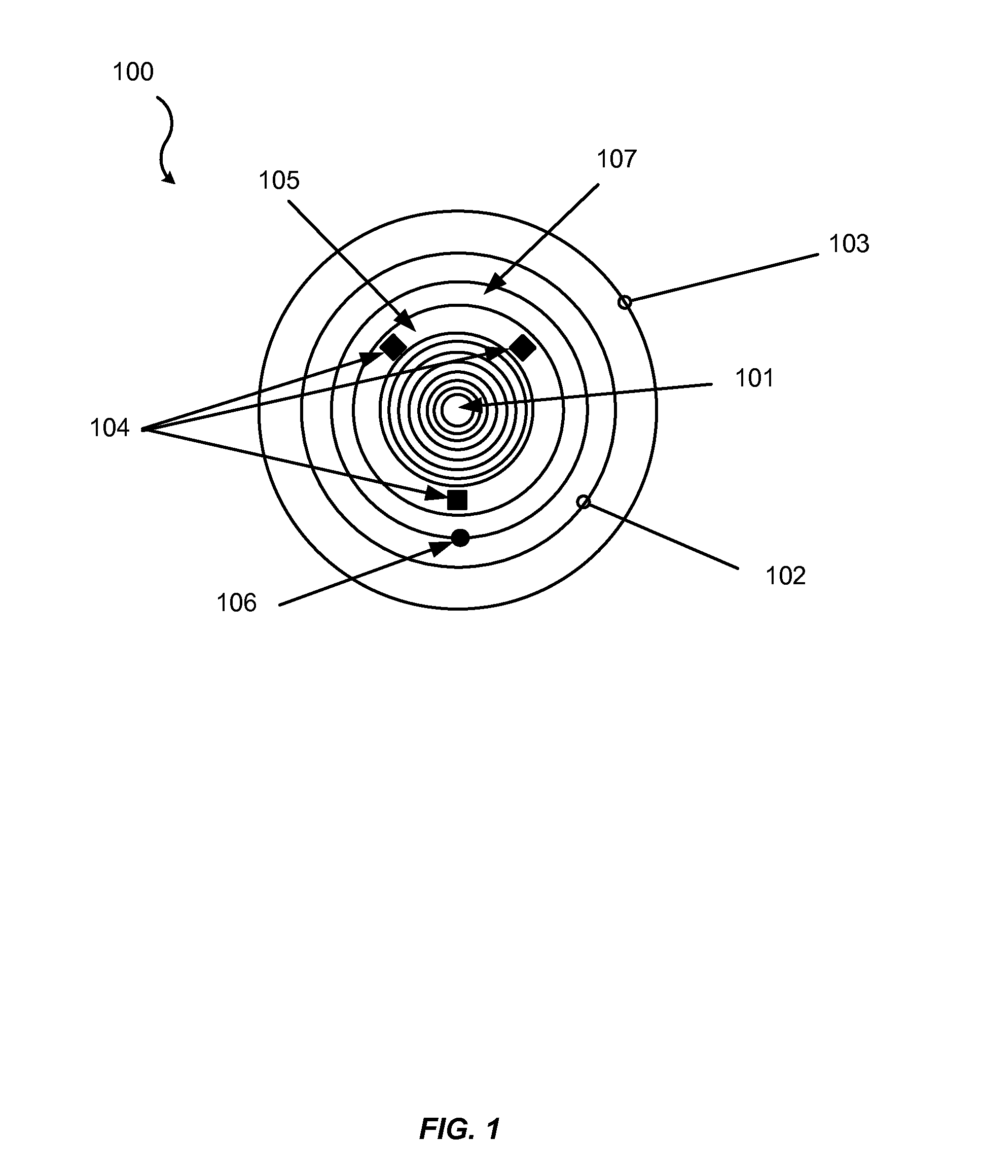
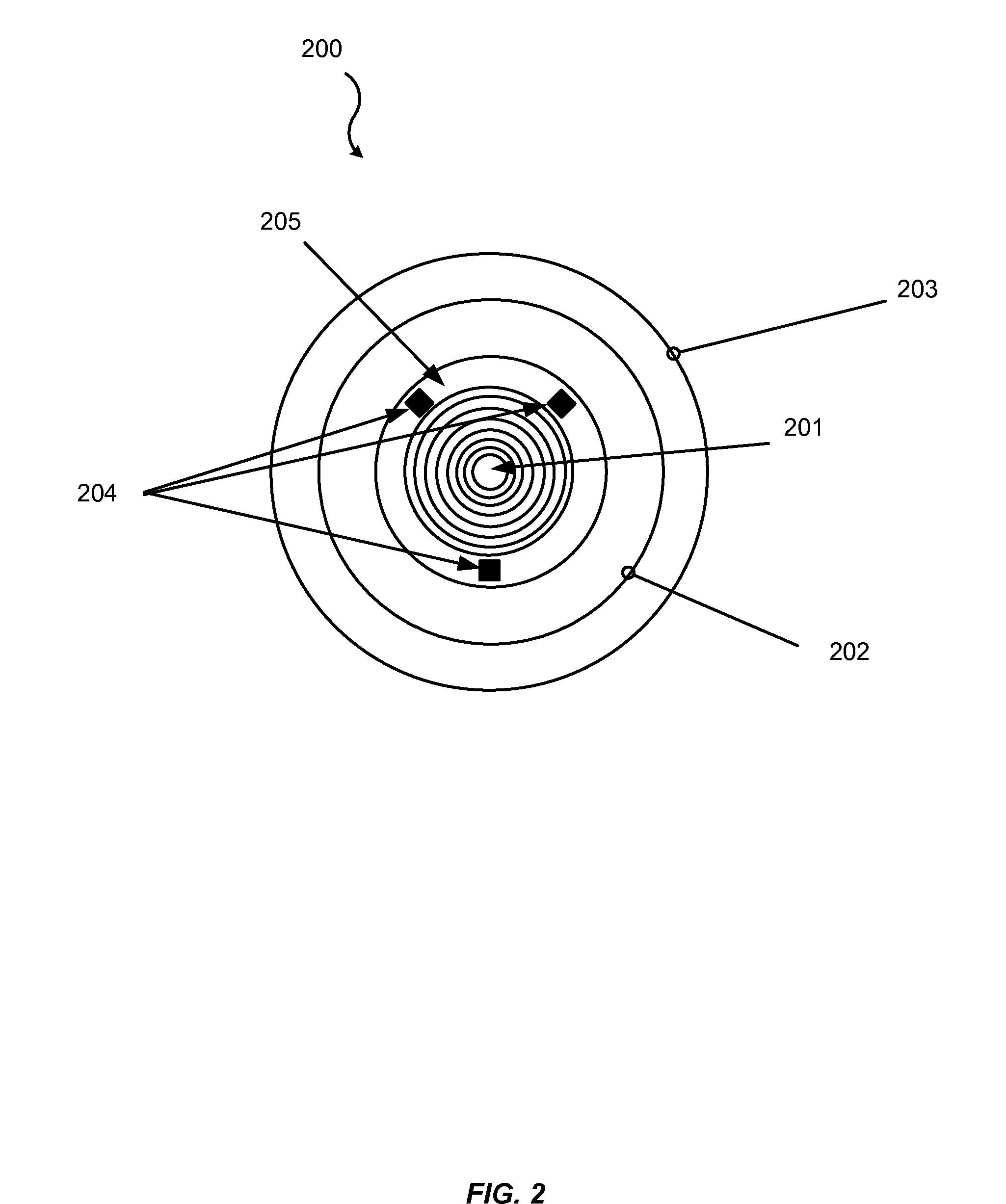
[0077]Embodiments described herein may provide a device or apparatus, such as a contact lens or intraocular lens, which includes a dynamic optic (such as a fluid lens) and an electronic component that may drive the dynamic optic such that at least a portion of the device may provide a dynamic optical power for a wearer. Some embodiments may also include a self-contained electronics module that comprises the dynamic optic (or a portion thereof) and / or the electronic component. The self-contained electronics module may have a thickness such that it may be utilized within a contact lens or an intraocular lens, such as a thickness that is less than 125 microns. The self-contained electronics module may contain components for utilizing the dynamic lens, such as a power source, sensor, and / or a controller.

[0078]The dynamic optic may utilize any suitable method of changing the focal length of an optical device (or a portion thereof). For example, as noted above some embodiments of a dynami...


PUM


Abstract

In some embodiments, a first device may be provided. The first device may include a first lens that comprises a contact lens or an intraocular lens. The first lens may include an electronic component and a dynamic optic, where the dynamic optic is configured to provide a first optical add power and a second optical add power, where the first and the second optical add powers are different. The dynamic optic may comprise a fluid lens.

Description

CROSS-REFERENCES TO RELATED APPLICATIONS[0001]This application claims benefit under 35 U.S.C. §119(e) of U.S. provisional patent application No. 61 / 408,764, filed on Nov. 1, 2010; and U.S. provisional patent application No. 61 / 410,466, filed on Nov. 5, 2010. The entire disclosure of each of these applications is incorporated herein by reference for all purposes and in their entireties.BACKGROUND OF THE INVENTION[0002]In general, both intraocular lenses and contact lenses may provide a sufficient means of vision correction for myopes, hyperopes and astigmats (i.e. individuals afflicted with any of the corresponding vision impairments) and are widely used for vision correction by younger people. This appears to be especially true in developed countries, where individuals may have better access to intraocular lenses and contact lenses (which may be more expensive, or more difficult to obtain in less developed countries). Typically, intraocular lenses and contact lenses may not be comfo...

Claims


Application Information

Patent Timeline
Patent Type & Authority Applications(United States)
IPC IPC(8): G02C7/04
CPCA61F2/1624A61F2/1648G02C7/085G02C7/08G02C7/04A61F2210/009A61F2250/0001A61F2250/0002
Inventor BLUM, RONALD D.
Owner HPO ASSETS
Why Eureka
Try Eureka