

Spatial Spectral Photonic Receiver for Direction Finding via Wideband Phase Sensitive Spectral Mapping
a phase sensitive spectral mapping and receiver technology, applied in the direction of optical radiation measurement, interferometric spectrometry, instruments, etc., can solve the problems of ineffective conventional direction finding and signal intercept methods
- Summary
- Abstract
- Description
- Claims
- Application Information
AI Technical Summary
Benefits of technology
Problems solved by technology
Method used
Image

Examples
Embodiment Construction
[0002]This invention was made with Government support under Contract No. N00014-07-1-1224 awarded by the Office of Naval Research of the Department of the Navy. The Government has certain rights in the invention.
BACKGROUND OF THE INVENTION
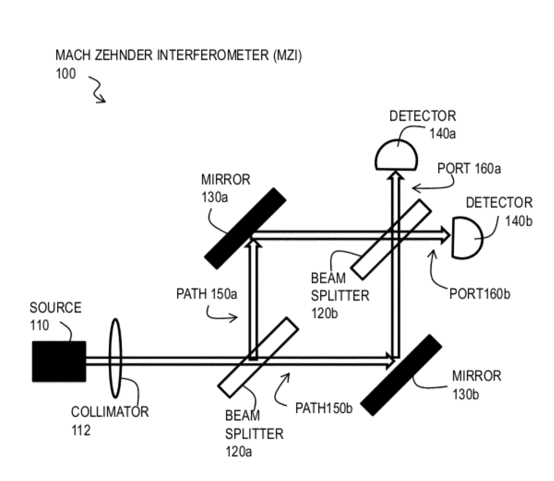
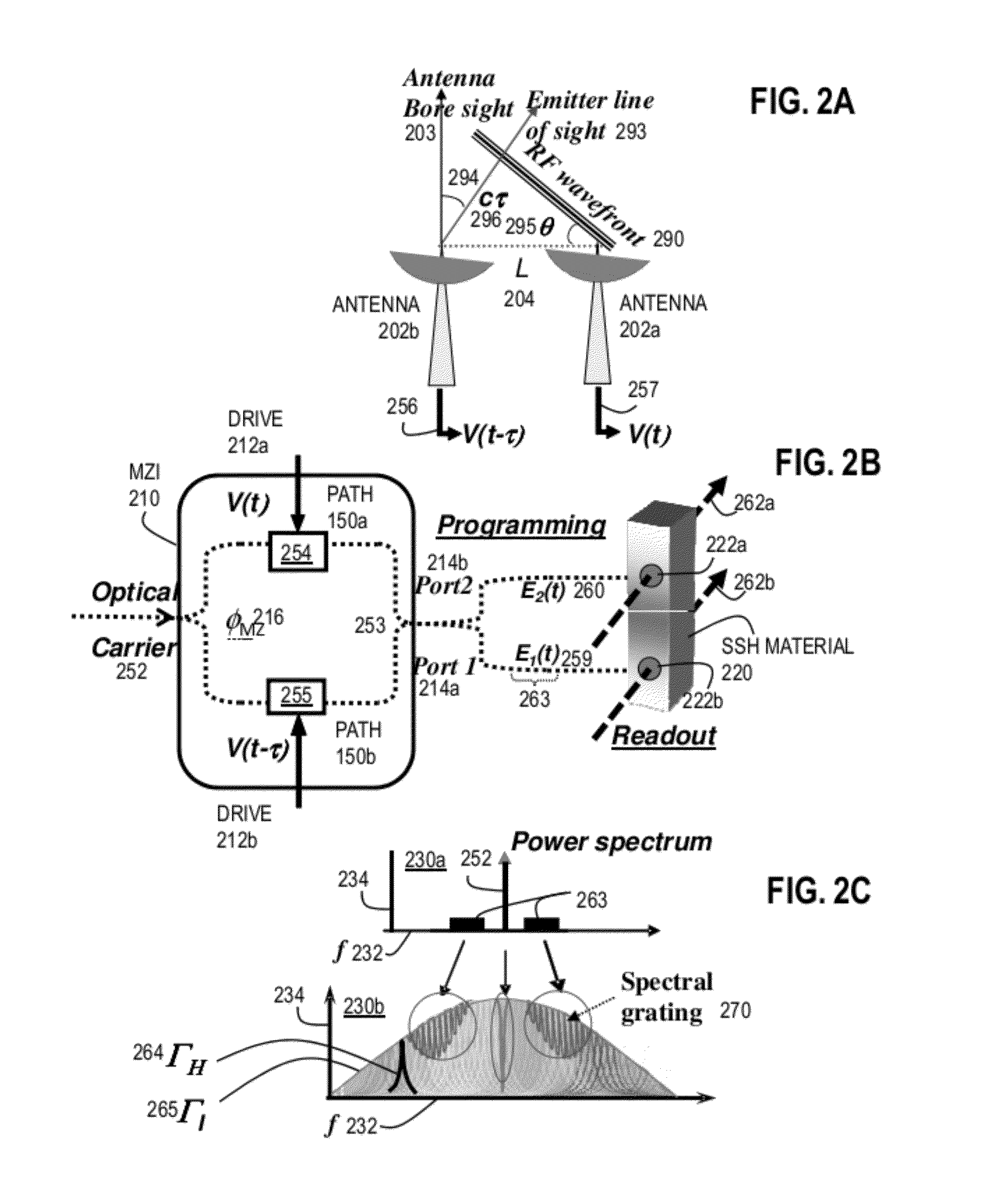
[0003]An electronic surveillance system monitoring a complex environment of radio frequency (RF) signals should be able to accurately and simultaneously locate each source of radiation, whether the source is a radar, a communication signal, or a jammer. The receiver system should be able to handle signals with varied and unknown formats operating over a broad frequency range, desired over several to tens of GHz now, and extending to >100 GHz in the future. Rapid assessment is desirable so the coordinates of signals of interest (SOI) can queue other sensors, such as imagery, listening, and radar systems. Reconnaissance platforms should discriminate multiple such complex signals operating over wide bandwidth frequency spans and deal with advanced, br...
PUM
 Abstract
Description
Claims
Application Information