Display device using a dihedral corner reflector array optical element

Active Publication Date: 2012-06-07
STANLEY ELECTRIC CO LTD +1
View PDF2 Cites 13 Cited by
  • Summary
  • Abstract
  • Description
  • Claims
  • Application Information

AI Technical Summary

Benefits of technology

[0018]Namely, there is obtained the advantageous effect of the invention demonstrated effectively when partial light beams seen by a view with a positional relation of a regular reflection with respect to the dihedral corner reflector array optical element are weaken in intensity within light beams irradiated to the main surface of the dihedral corner reflector array optical element at the viewer side.
[0019]In addition, it is preferable to provide respectively metal reflective films on the plane sides of the protrudent body functioning as the dihedral corner reflector, since there is an increase in intensity of light complicatedly reflected by the convex structure of the protrudent bodies thereby the advantageous effect of the invention is demonstrated effectively.
[0020]According to the invention, the display device using the dihedral corner reflector array optical element with the protrudent bodies enables a viewer to observe a floating image of real image in condition it can be easily seen.

Problems solved by technology

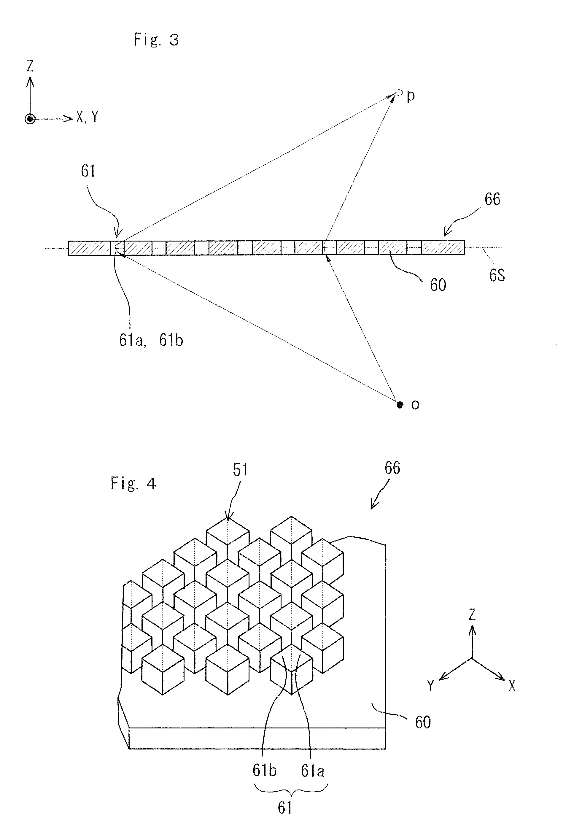
However, there is a problem that it is difficult to see the floating image by using the dihedral corner reflector of tubular body as shown in FIG. 4, so that a real image with a feeling of float in the air is insufficient.
Namely, the inventors have found a problem of difficulty in seeing a floating image is caused by the asymmetry in that the protrudent tubular body-side has an uneven structure of (e.g., rows of plural cubic shape tubular bodies) at one side but at the other side, i.e., substrate-side is a smooth main surface.

Method used


Image

  • Display device using a dihedral corner reflector array optical element
  • Display device using a dihedral corner reflector array optical element
  • Display device using a dihedral corner reflector array optical element

Examples


embodiments

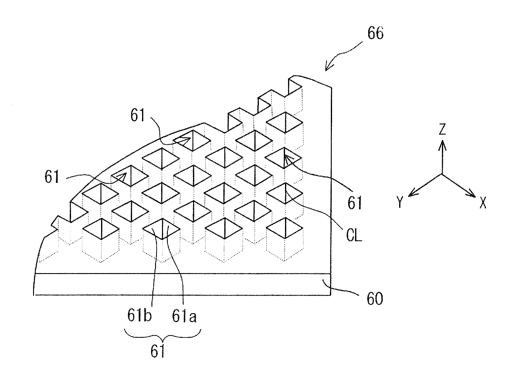
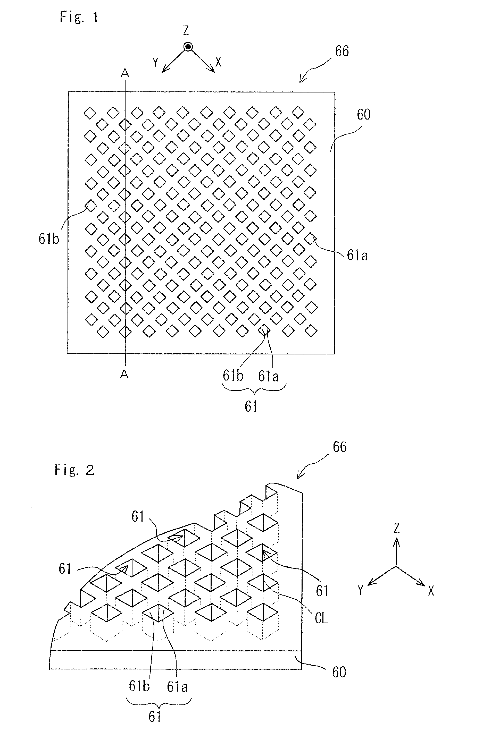
[0050]FIG. 13 shows a schematic structure diagram illustrating a display device using the dihedral corner reflector array optical element as an embodiment. As shown in FIG. 13, the dihedral corner reflector array optical element 66 and the object 4 are positioned at an opposite side to the viewer side. A real image 5 (real specular image) of the object 4 is formed in a space of the viewer-side (a viewer's sightline is indicated by an arrow) with respect to the dihedral corner reflector array optical element 66 according to the foregoing principle, so that the viewer can see a floating image 5. The observed 4 may be a real body and the object 4 may be a picture exhibited in a display surface of a liquid crystal display panel or the like. FIG. 14 illustrates a state that a viewer is observing the display device of FIG. 13 with a floating image caused thereby when viewed from the viewer's sightline (an arrow in the figure). FIG. 14 shows that when a dog picture as an object 4 is exhibi...


PUM


Abstract

A display device includes a dihedral corner reflector array optical element composed of a substrate and a plurality of dihedral corner reflectors arranged regularly on one main surface of the substrate, the dihedral corner reflectors including orthogonal mirror planes perpendicular to each other and being perpendicular to the main surface of the substrate; and an object existing by the one surface of the substrate, the optical element forming a real image of the object by the other main surface of the substrate. The optical element includes a plurality of protrudent bodies integrally formed of a transparent material of the substrate, each of the protrudent bodies including two sides of orthogonal mirror planes perpendicular to each other as the dihedral corner reflector perpendicular to the main surface of the substrate. The optical element is disposed so that the protrudent bodies face toward a space in which the object exists.

Description

BACKGROUND OF THE INVENTION[0001]1. Field of the Invention[0002]The present invention relates to a reflective real specular image forming element forming a real image (real specular image) of an observed object in a space of a viewer side, and more particularly to a display device using a dihedral corner reflector array optical element.[0003]2. Description of the Related Art[0004]There have been suggested a display device for allowing a viewer to see a real image (real specular image) of an observed object in air (see Patent Publication WO2007-116639).[0005]Specifically, such a display device comprises a reflective real specular image forming element performing the formation of a real image (real specular image) of an observed object in a space of a viewer side; and the observed object disposed in a space opposite to the viewer side with respect to the reflective real specular image forming element.[0006]The document WO2007-116639 discloses a reflective real specular image forming e...

Claims


Application Information

Patent Timeline
IPC IPC(8): G02B5/136
CPCG02B5/136
Inventor SUGIYAMA, TAKASHIMAEKAWA, SATOSHI
Owner STANLEY ELECTRIC CO LTD
Why Eureka
Try Eureka