
Drag-type wind turbine for wind-driven electricity generators and wind-driven electricity generators using drag-type wind turbine

a technology of wind turbines and wind turbine blades, which is applied in the direction of wind motors with perpendicular air flow, non-positive displacement fluid engines, liquid fuel engine components, etc., can solve the problems of not always getting enough wind, emitted noise and low-frequency waves, and a risk to human health, so as to improve the efficiency of wind power and efficient wind streaming

Inactive Publication Date: 2012-06-07
MARUYOSHI SHOKAI
View PDF7 Cites 2 Cited by
  • Summary
  • Abstract
  • Description
  • Claims
  • Application Information

AI Technical Summary

Benefits of technology

[0031]The first aspect of this invention is drag-type wind turbine blades for a wind-driven electricity generator, which are vertically provided between at least two plates provided in the air of which the wind turbine blades of a plate-like structure and a fin-shaped surface comprising a wind receiving side to receive wind, and a wind streaming side located on the back of the wind receiving side, and a base end of the wind receiving side and a connecting side to connect the base end of the wind streaming side, characterized in that the wind receiving side comprises a base section, and a base concave-shaped wind receiving section that is sunken at a sharp angle from the free end of the base section, and an concave-shaped wind receiving section in the shape of an inverse parabola extending in the radiation direction, and the wind streaming side has a convex-shaped wind streaming section that is gently formed in the shape of a parabola extending from the base section toward the end of the radiation direction, and the connecting side comprises a concave-shaped connecting section in the shape of an inverse parabola extending toward both base ends.
[0032]Therefore, the first aspect of this invention has a feature to receive wind by wind turbine blades so that wind received upon the blades makes a whirling jet of air (whirling current) to be a weir thus increasing the wind power upon a concave-shaped section that is receiving the wind, thus using efficiently wind power or the like. The first aspect of this invention also has a feature to stream wind upon the convex surface of the blades, and to stream such wind upon the concave-shaped section of the blades that are receiving the wind, thus using efficiently the wind streaming along the convex-shaped section of the blades. Furthermore, the first aspect of this invention has a feature to makes it possible for the wind to stay longer upon the wind turbine blades, thus almost fully using and not wasting the natural wind, thus providing drag-type wind turbine blades for wind-driven electric power generators, thus economically using the wind power.
[0033]The second aspect of this invention is also drag-type wind turbine blades for a wind-driven electricity generator, according to the first aspect of this invention, characterized in that a concave condition of the base concave-shaped wind receiving section of the blades, a caving direction of the concave-shape wind receiving section and a bulging direction of the convex-shaped wind receiving section of the blades are determined based on reference line A provided on the top surface of the wind turbine blade.
[0034]Therefore, the second aspect of this invention has a feature to achieve the first aspect of this invention and to provide examples of the most appropriate concave condition of the turbine blades, of the concave-shaped wind receiving section, and of the convex-shaped wind receiving section.
[0035]The third aspect of this invention is drag-type wind turbine blades for a wind-driven electricity generator according to the first aspect of this invention, characterized in that a caving direction of the concave-shaped connecting section of the blades is determined based on reference line B provided between the base ends of the wind receiving side and of the wind streaming side.
[0036]Therefore, the third aspect of this invention has a feature to achieve the first aspect of this invention and to provide examples of the most appropriate concave-shaped connecting section of the blades.

Problems solved by technology

The disadvantages of both the drag-type and lift-type rotary blades are that they do not always get enough wind to rotate them, and they pose a risk to human health by their emission of noise and low-frequency waves.
There is also the risk of handling them during natural disasters, for example, in typhoon rains and strong winds.

Method used


Image

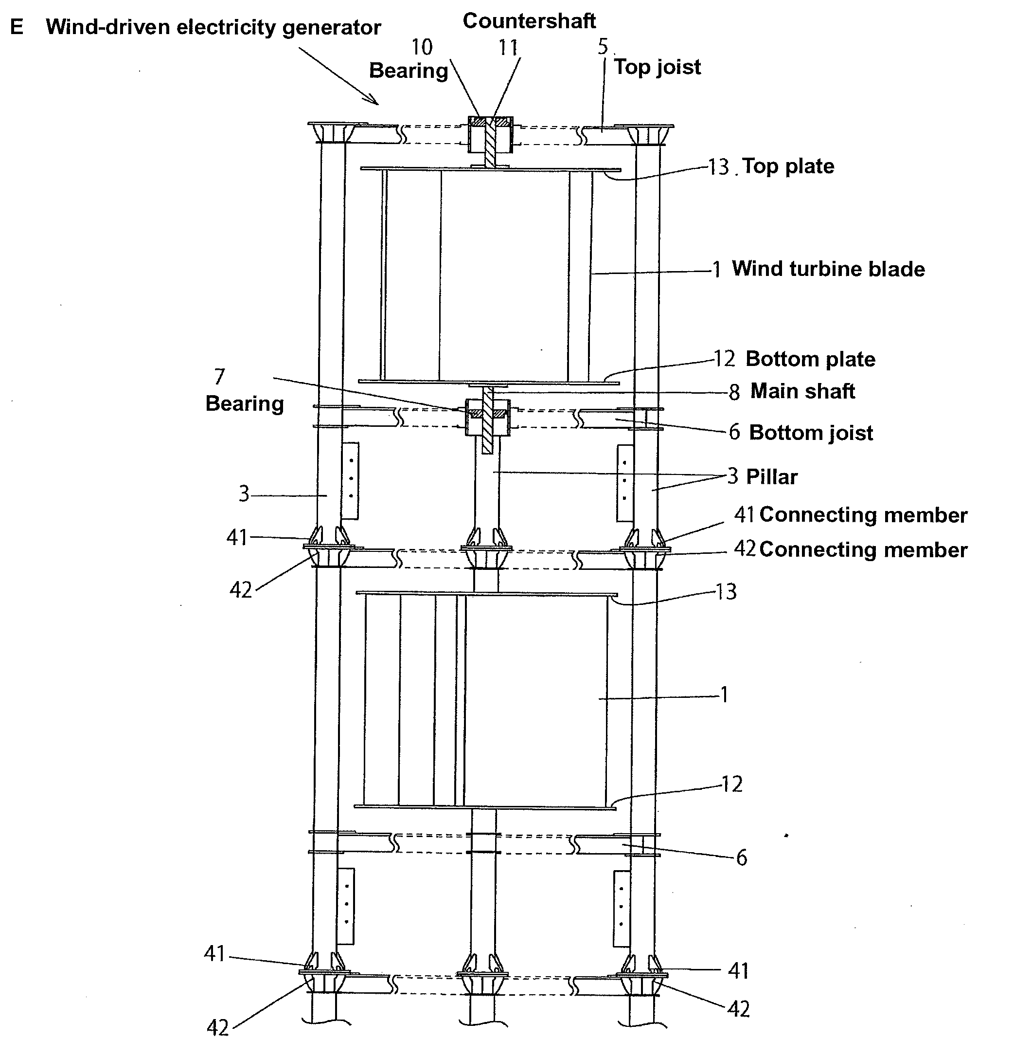
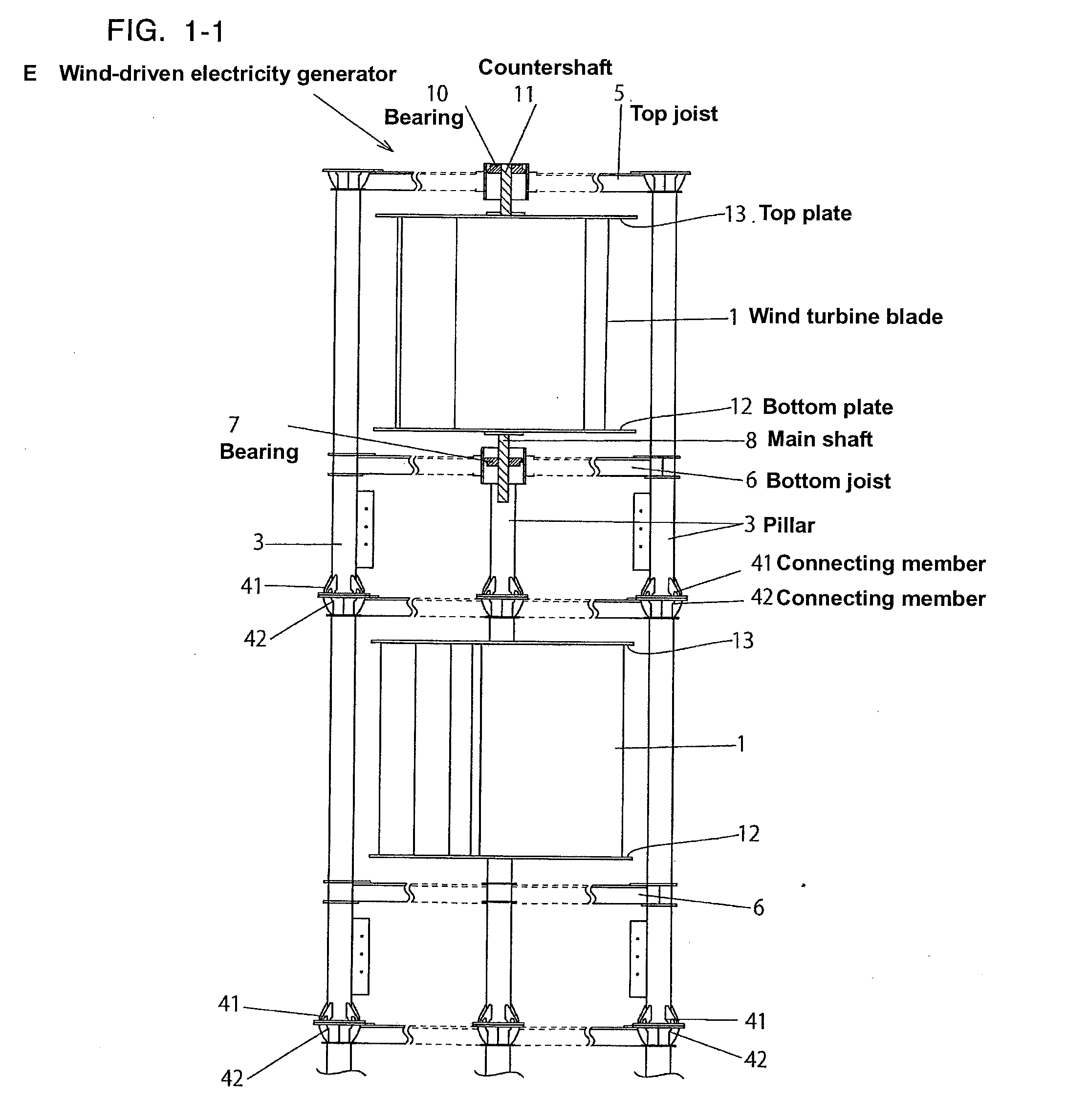
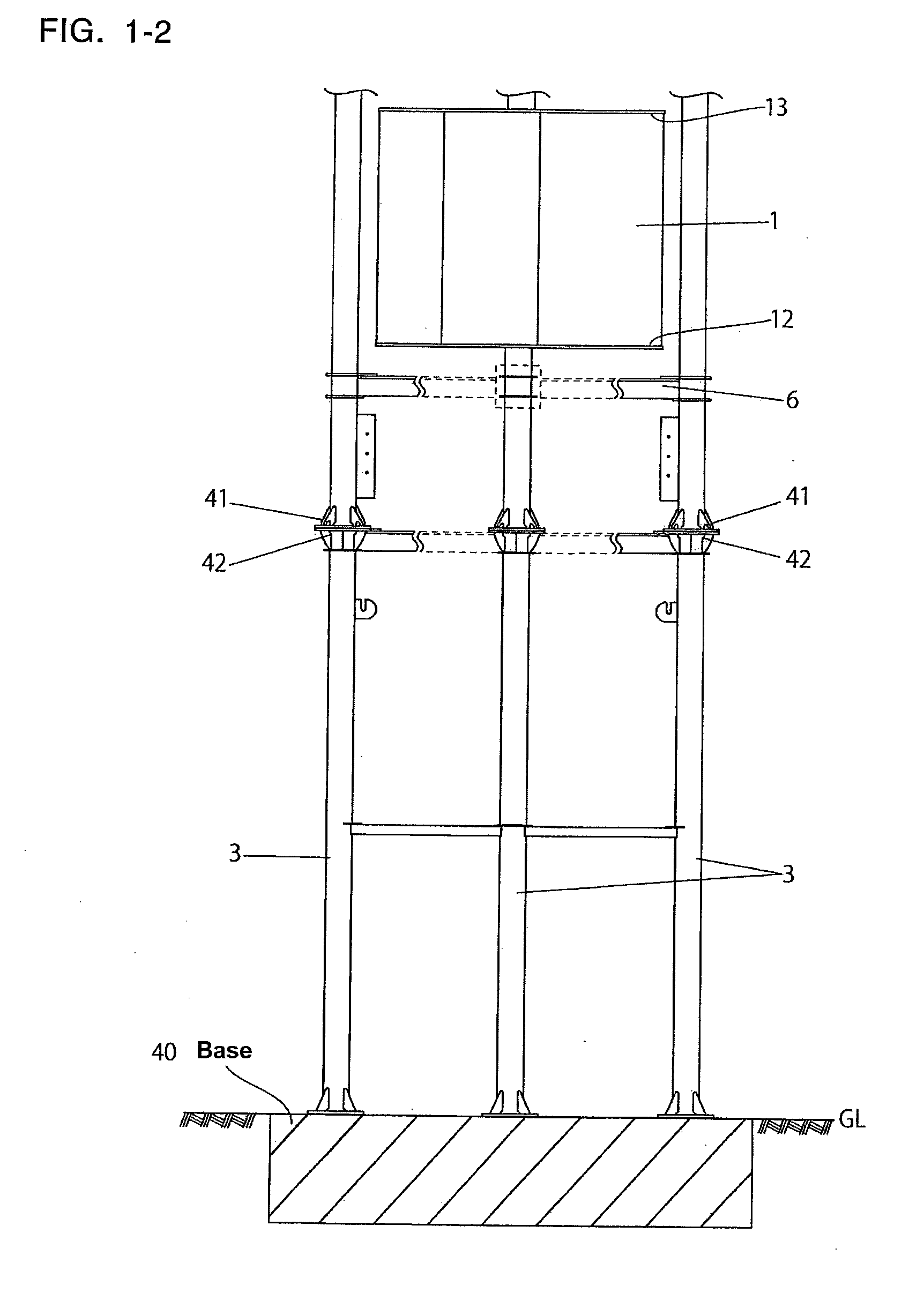
  • Drag-type wind turbine for wind-driven electricity generators and wind-driven electricity generators using drag-type wind turbine
  • Drag-type wind turbine for wind-driven electricity generators and wind-driven electricity generators using drag-type wind turbine
  • Drag-type wind turbine for wind-driven electricity generators and wind-driven electricity generators using drag-type wind turbine

Examples


Embodiment Construction

[0067]The preferred embodiments of the invention are described below.

[0068]Firstly, (referring to FIG. 6) the overall structure of wind turbine blades 1 that are commonly used for the embodiments in this invention is that end surface X of each blade is fin-shaped (comma-shaped) C and longitudinal direction Y is of plate D like a horizontal blade on an excavator. The preferred outer structure of turbine blades 1 is described below.

[0069]Wind turbine blade 1 integrally comprises wind receiving side 1a of concave shape, wind streaming side 1b of convex shape located behind wind receiving side 1a, base end 1a1 of wind receiving side 1a, base end 1b1 of wind streaming side 1b, and connecting side 1c. The preferred structure, combining wind receiving side 1a, wind streaming side 1b and connecting side c is described below.

[0070]Wind receiving side 1a integrally comprises base section 100 located near blade core 1d and straightly extending in parabolic direction Z and slanting upward, and ...


PUM


Abstract

Drag-type wind turbine blades for wind-driven electricity generators are vertically provided between plates of the generator. The wind turbine blades have a plate-like structure with a fin-shaped surface. The turbine blade comprises a wind receiving side consisting of a base section, a base concave-shaped wind receiving section, a convex-shaped wind streaming section, and a wind streaming side of a convex-shaped surface extending in a radiation direction on the back of the wind receiving side. The base end of the wind receiving side and the connecting side comprise an inverse parabolic concave-shaped connecting section to connect it to the base section of the wind streaming side.

Description

FIELD OF INVENTION[0001]This invention relates to drag-type wind turbine blades used in wind-driven electricity generators and wind-driven electricity generators using drag-type wind turbine blades.BACKGROUND OF THE INVENTION[0002]As is well known, wind-driven electricity generators (wind-power generation) using rotary blades (vanes, turbine blades or the like) attract much attention since they require no natural resources and emit no CO2 (carbon dioxide). Wind-driven electricity generators using rotary blades are generally known as drag-type rotary blades and lift-type rotary blades. Each has its advantages and disadvantages. The advantages of the drag-type rotary blades are that its sails require less wind to make much electricity without emitting noise or low-frequency waves. The disadvantages of both the drag-type and lift-type rotary blades are that they do not always get enough wind to rotate them, and they pose a risk to human health by their emission of noise and low-frequen...

Claims


Application Information

Patent Timeline
Patent Type & Authority Applications(United States)
IPC IPC(8): F03D3/06F03D11/02F03D80/00
CPCF03D3/02Y02E10/74F05B2240/40F03D3/065F03D3/062F03D80/70F03D9/25F03D9/11F03D9/34
Inventor YASUI, EIICHI
Owner MARUYOSHI SHOKAI
Learn More