

Fiber reinforced resin, manufacturing method for fiber reinforced resin, and manufacturing system for fiber reinforced resin
- Summary
- Abstract
- Description
- Claims
- Application Information
AI Technical Summary
Benefits of technology
Problems solved by technology
Method used
Image

Examples
first embodiment
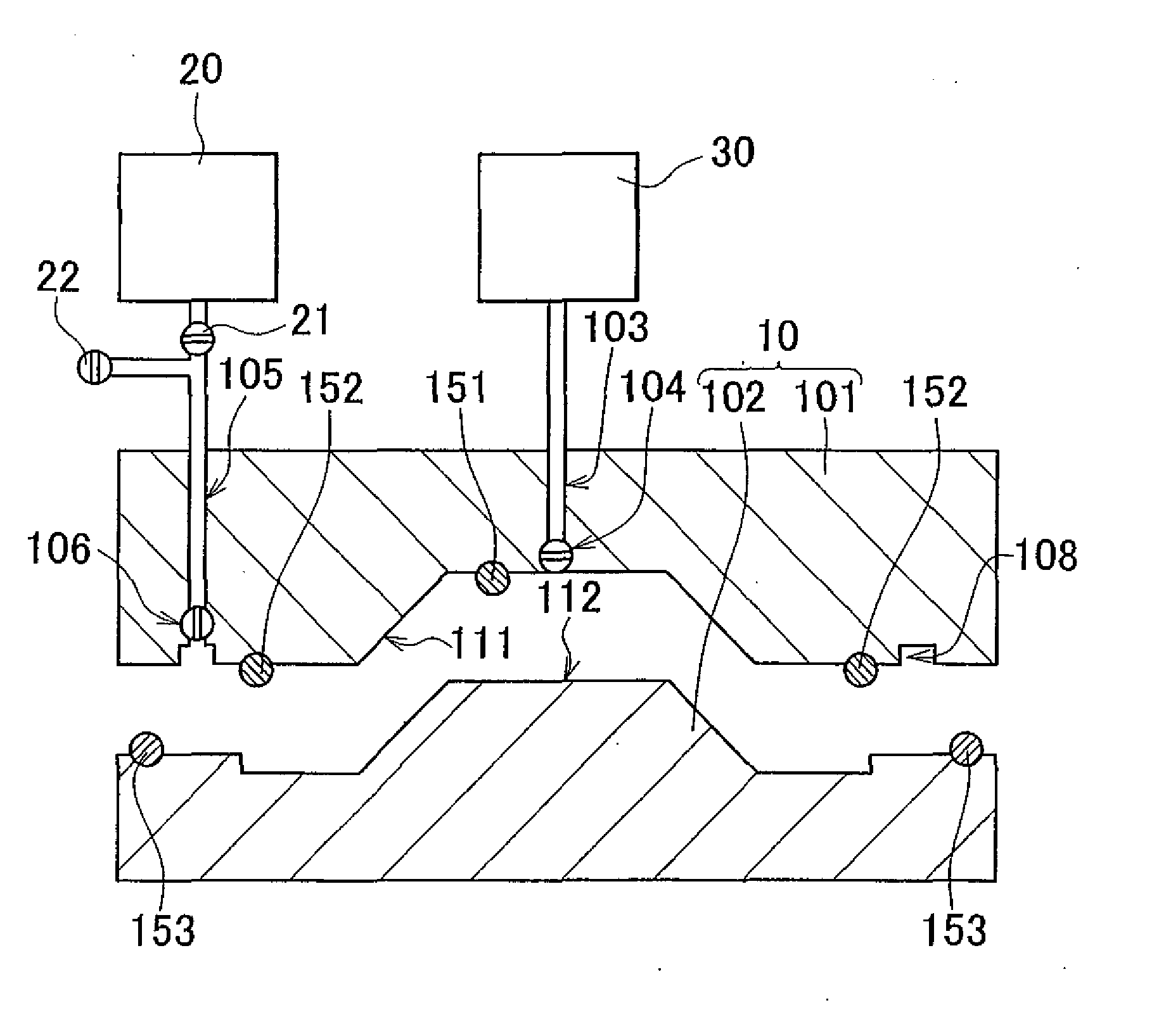
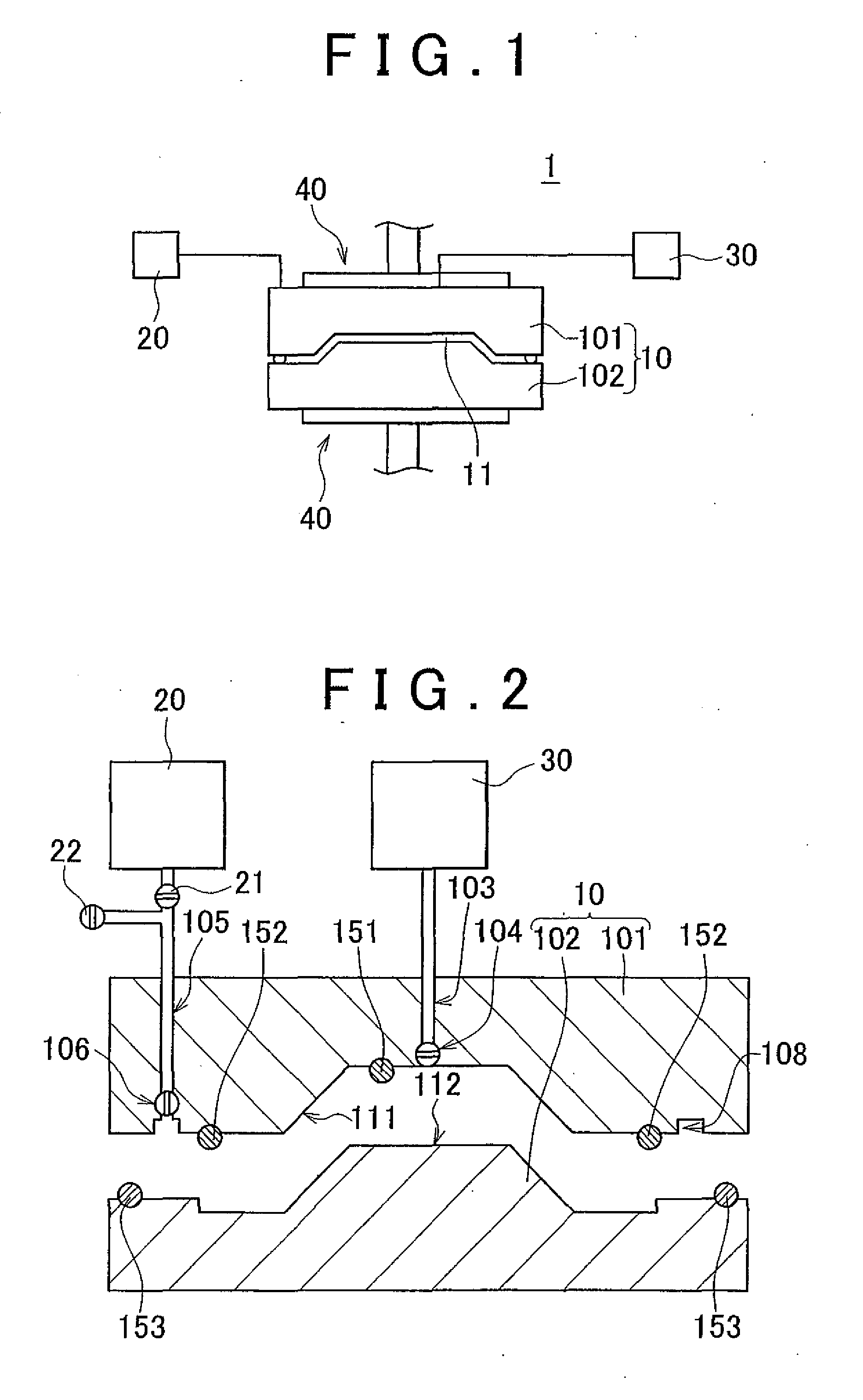
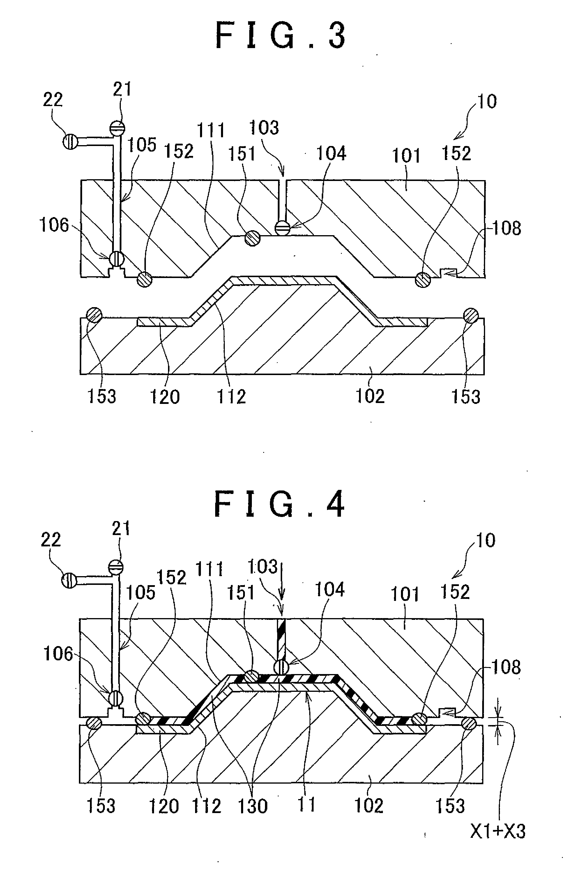
[0030]Hereinafter, the invention will be described with reference to the accompanying drawings. FIG. 1 is a view that shows a manufacturing system 1 for a fiber reinforced resin according to the present embodiment. The manufacturing system 1 includes a molding die 10, a decompressor 20, a resin injector 30, and a die closer 40. The decompressor 20 and the resin injector 30 are connected to the molding die 10. The die closer 40 applies pressure to the molding die 10 in the vertical direction. The molding die 10 includes an upper die 101 and a lower die 102. A cavity 11 is formed between the upper die 101 and the lower die 102. The cavity 11 has a shape corresponding to the shape of a product. The manufacturing system 1 injects resin into the cavity 11 defined by the upper die 101 and the lower die 102, and cures the resin while applying pressure to the resin using the die closer 40, thus molding the injected resin. The die closer 40 includes position adjusting means (not shown) and c...
second embodiment
[0049]In the second embodiment, in the first process, as shown in FIG. 7, a resin diffusion medium 521 is placed on the cavity surface 512 of the lower die 502, and a fiber reinforced base 520 that contains a core material 522 therein is placed on the resin diffusion medium 521. The core material 522 may be, for example, rigid urethane foam or polymethacrylic foam. The fiber reinforced base 520 may be, for example, carbon fiber.
[0050]The resin diffusion medium 521 is placed in order to ensure a space for allowing resin to flow between the fiber reinforced base 520 and the cavity surface 512 of the lower die 502. The resin diffusion medium 521 may be, for example, nylon mesh having a thickness of 0.8 mm and an open area ratio of 80 percent or above.
[0051]When the molding die 50 is used, in the first process, as resin is injected through the resin injection passage 503 formed in the upper die 501, the fiber reinforced base 520 and the core material 522 are pressed against the cavity s...
PUM
| Property | Measurement | Unit |
|---|---|---|
| Mass | aaaaa | aaaaa |
| Area | aaaaa | aaaaa |
| Distance | aaaaa | aaaaa |
Abstract
Description
Claims
Application Information