Two-dimensional symbol code and method for reading the symbol code

a symbol code and two-dimensional technology, applied in the field of two-dimensional symbols, can solve the problems of insufficient robustness, inability to recover read errors, and inability to be corrected, and achieve the effects of short clock time in production, easy operation, and high degree of involvemen

Inactive Publication Date: 2012-06-14
CONTINENTAL TEVES AG & CO OHG
View PDF5 Cites 64 Cited by
  • Summary
  • Abstract
  • Description
  • Claims
  • Application Information

AI Technical Summary

Benefits of technology

[0074]By contrast, a vector-oriented method operates “without removal”, which is why lines and surface areas can be burned quickly. For the example above, only three to five seconds of time are required, for example, which, depending on the laser and the required power, can also be significantly lower. In order to achieve short clock times in production, the use of a vector-oriented method therefore makes sense. For this reason, the individual symbols are designed, in accordance with aspects of the invention, such that vector-oriented drawing of these symbols is possible. In accordance with one preferred embodiment, they therefore each contain only two cohesive surface areas, of which, in accordance with aspects of the invention, one surface area needs to be machined and the other surface area remains unmachined. A symbol can therefore be drawn in one move without removing the laser.
[0075]A further criterion for the selection of the graphical symbols is a technical restriction in the process of lasering. The edges between machined and unmachined surface areas are not clear-cut, since powder traces produced during burning react with the material in the surroundings or the movement of the laser does not run exactly and thus additional regions are machined which are not intended to be. In this case, machined regions can erode and merge continuously into unmachined object regions, or the majority of the latter can even be covered by surrounding machined reg...

Problems solved by technology

For the same reason, soiling results in unrecoverable read errors.
Although a read error can therefore be noticed, it cannot be corrected, which is why they are not sufficiently robust for the purpose cited at the outset.
In the case of stacked codes, however, the scan line for the read operation needs to be exactly above the equivalent graphical symbol line, which limits the compactness which can be achieved thereby.
This increases susceptibility to error, however, since the nonrecognition of a symbol can lead to the assumption that the other symbol is coded at that point, even if there is merely soiling or overlay, for example.
If laser technology is used to directly burn the graphical symbols of such a machine-readable code onto a mechanical or electronic component, it is necessary to take account of limitations related to process engineering which affect the optical quality of the applied markings and adversely affect later decoding of the individual symbols by an image processing system.
Similar concepts are also used in other methods, with the problem arising that it is necessary to find local maxima for the filter responses.
In addition, the topological position of said filter responses also cannot be exactly predicted in the local region of expected neighbors.
Therefore, the ordinarily tracked approaches and analysis methods regularly give rise to problems in the decoding, particularly if the external circumstances are not optimum, for example as a result of reflections or curved surfaces.
Both previously indicated methods for extracting symbol centers have the drawback that only pixels with values above a global th...

Method used


Image

  • Two-dimensional symbol code and method for reading the symbol code
  • Two-dimensional symbol code and method for reading the symbol code
  • Two-dimensional symbol code and method for reading the symbol code

Examples


Embodiment Construction

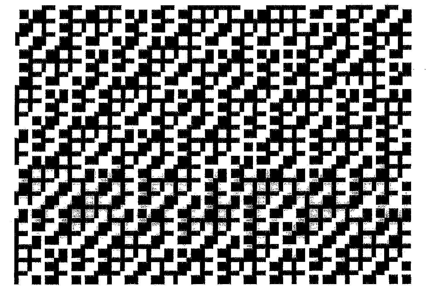
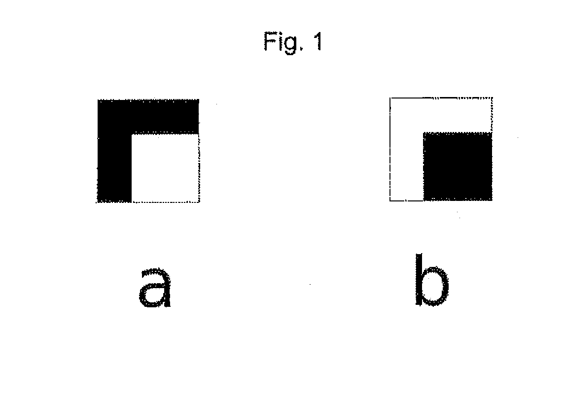
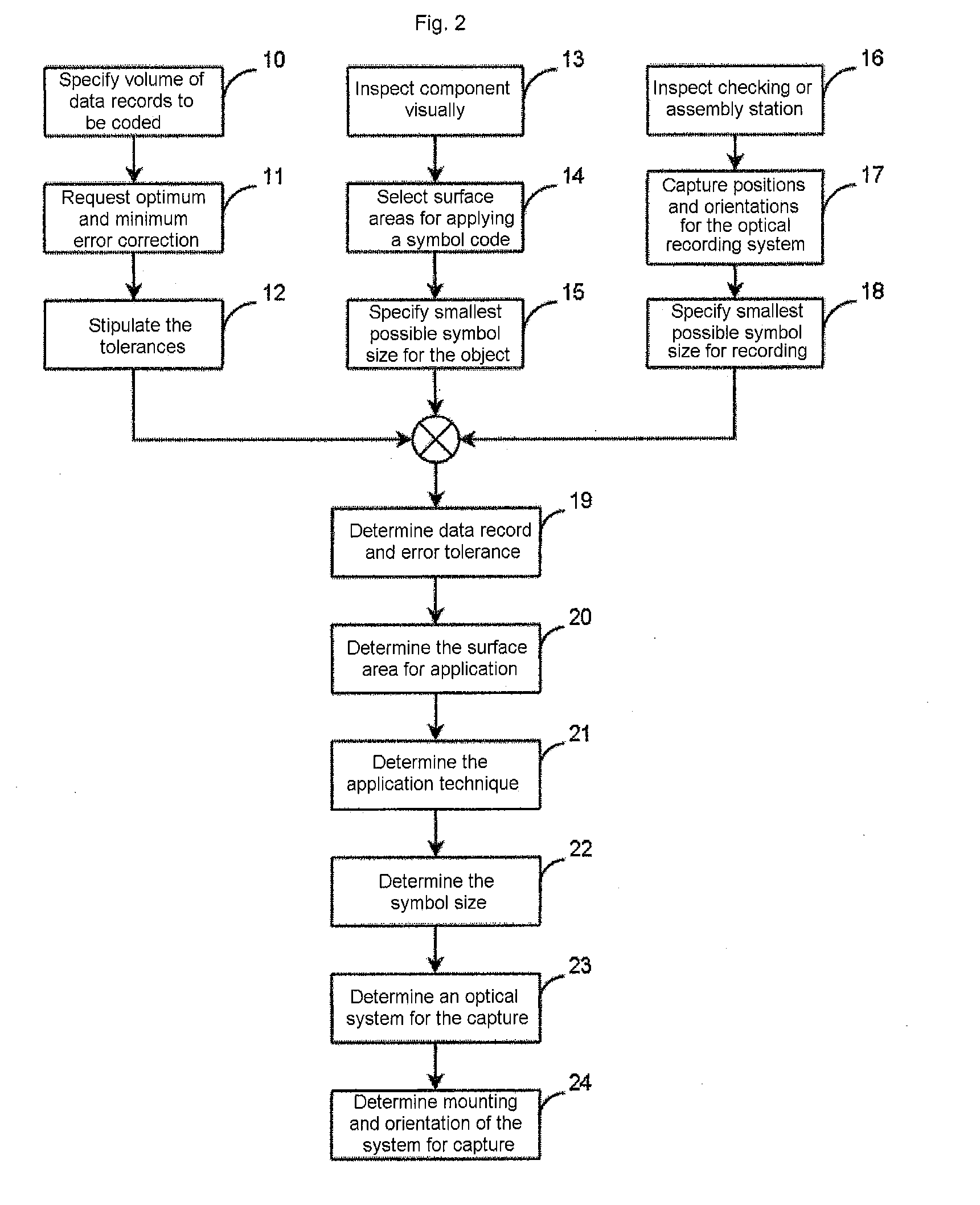
[0149]FIG. 1 shows the graphical symbols or symbol types for binary zero- and one-words. From these two symbols, any arbitrarily shapable symbol code is produced. FIGS. 2 to 4 and FIG. 7 show the process of decision-making for a symbol code and the incorporation into the production process as flowcharts. FIGS. 5 and 6 show specific examples of the application of a symbol code to a particular component, with the variability and versatility becoming clear in the application of the specified symbol code.

[0150]Differently shaped symbol codes, as shown by way of example in FIGS. 8 to 11 and 13, can be integrated into a production process without any problem, FIG. 15 and the flowchart from FIG. 7 describing the production and association of surface area histograms with the various symbol codes. An algorithm for decoding the binary words represented by symbols can only deal with symbol codes of a particular shape in each case, so that the surface area histogram of the recognized symbol cod...


PUM


Abstract

The specification describes a two-dimensional symbol code for representing binary data, which symbol code is constructed from a plurality of graphical symbols arranged next to one another, wherein the symbol code is formed from precisely two different symbols having the same surface area which differ in their areal brightness distribution and each code a value from a binary data word. The symbols have a complementary brightness distribution. In a method for reading this two-dimensional system code, the system code has a filter applied to it which matches the brightness distribution of one of the two complementary symbols, wherein in the event of a match one symbol is recognized and in the event of no match the other symbol is recognized.

Description

CROSS REFERENCE TO RELATED APPLICATION[0001]This application is the U.S. National Phase Application of PCT / EP2009 / 054271, filed Apr. 8, 2009, the contents of such applications being incorporated by reference herein.FIELD OF THE INVENTION[0002]The invention relates to a two-dimensional, in particular machine-readable, symbol code for representing binary data, which symbol code is constructed from a plurality of graphical symbols arranged next to one another in a preferably horizontal and / or vertical direction, wherein the symbol code is formed from precisely two different symbols having the same surface area which differ in their areal brightness distribution and each code a value from a binary data word. In addition, the invention describes a method for reading said symbol code, a particularly preferred use and a suitable reading apparatus.BACKGROUND OF THE INVENTION[0003]In order to automate the production and quality checking of products, single components which are assembled on a...

Claims


Application Information

Patent Timeline
IPC IPC(8): G06K19/06G06F17/00G06K7/10G06V30/224
CPCG06K19/06037G06K19/06G06V30/224
Inventor BIETENBECK, FELIXZIMMERMANN, HERBERTWEIS, TORBENPAULI, JOSEFHERWIG, JOHANNES
Owner CONTINENTAL TEVES AG & CO OHG
Why Eureka
Try Eureka