Roller unit

a roller unit and roller technology, applied in the field of roller units, can solve the problems of shortening the service life of the seal and accelerating the wear of the seal, and achieve the effects of improving the ease of unit assembly, reducing wear, and simplifying the structure of the roller uni

Inactive Publication Date: 2012-06-14
KOMATSU LTD
View PDF4 Cites 18 Cited by
  • Summary
  • Abstract
  • Description
  • Claims
  • Application Information

AI Technical Summary

Benefits of technology

[0017]In the invention, the flange portion of the collar is in contact with the outer end face of the seal. With this arrangement, the flange portion of the collar prevents penetration of earth, sand, etc. into the seal slidable contact parts of the inner and outer circumference side sealing portions. Accordingly, the wear of the seal attributable to the penetration of earth, sand, etc. into the seal slidable contact parts can be restricted and, in consequence, the service life of the seal can be extended.
[0018]When fitting the seal in the annular space defined between the roller and roller shaft, only the end face of the inner circumference side sealing portion of the seal is pressed by the flange portion of the collar. Thanks to this, no load is imposed on the outer circumference side sealing portion so that the outer and inner circumference side sealing portions can be kept in a proper positional relationship. In consequence, the area extending between the outer and inner circumference side sealing portions can be properly sealed.
[0019]Further, the provision of the mounting portion in the collar that is secured to the track frame leads to an improvement in the ease of unit assemblability.
[0020]In addition, since the boss portion receives a thrust load from the roller, the structure of the roller unit can be simplified so that the seal can be smoothly fit in the annular space between the roller and the roller shaft without use of special tools, which results in an improvement in the ease of unit assemblability.
[0021]In addition, it is possible to avoid such an undesirable situation that the rotating side of the outer end face of the seal hits against the flange portion of the collar in the course of assembly, causing deformation of and damage to the seal. It is apparent that the same effect can be expected during traveling.

Problems solved by technology

Incidentally, if earth, sand or the like penetrates into the seal slidable contact parts of the inner and outer circumference side sealing portions, wear of the seal is accelerated, extremely shortening the service life of the seal.

Method used


Image

  • Roller unit
  • Roller unit
  • Roller unit

Examples


Embodiment Construction

[0029]Referring now to the accompanying drawings, a roller unit will be described according to a preferred embodiment of the invention. Although the following embodiment has been described in the context of a case where the invention is applied to roller units (track roller units) provided in a crawler track unit of a hydraulic excavator, the invention is not limited to this case but is equally applicable to roller units (track roller units) provided in a crawler track unit of other work vehicles such as bulldozers.

[0030](Outline of Crawler Track Unit of Hydraulic Excavator)

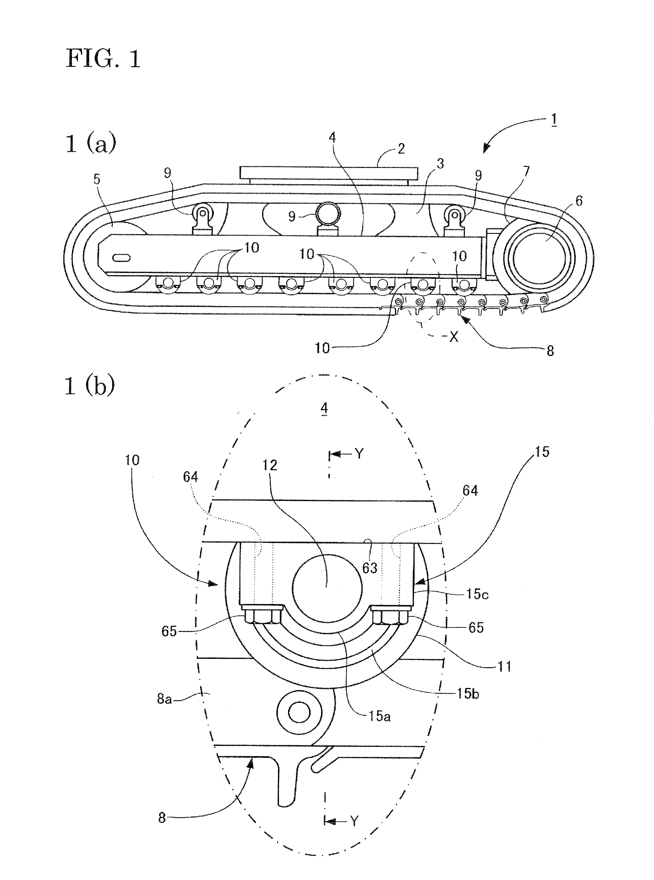
[0031]FIG. 1 shows a crawler track unit 1 which includes track frames 4 that extend in a longitudinal direction on the sides, respectively, of a center frame 3 (only the track frame located on the left side is shown). The center frame 3 has a mounting table 2 for a swing bearing (not shown) that is configured to rotatively support an upper machinery (not shown). In each track frame 4, an idler (idler tumbler) 5 i...


PUM


Abstract

[Subject] A roller unit is provided which is improved in the service life of the seal as well as in the ease of unit assemblability.[Means for Solving the Problem] A track roller unit 10 having a roller 11 configured to roll in contact with a crawler belt 8, a roller shaft 12 for rotatably supporting the roller 11, and a seal 14 fit in an annular space 26 defined between the roller 11 and the roller shaft 12; wherein the seal 14 is formed such that an inner circumference side sealing portion 30a located on an inner circumference side and an outer circumference side sealing portion 30b located on an outer circumference side are fit together so as to come into slidable contact with each other; which further comprises a collar 15 mounted to the roller shaft 12; and wherein the collar 15 has a boss portion 62 into which the seal 14 is pressed and a flange portion 15b in contact with an outer end face of the seal 14.

Description

TECHNICAL FIELD[0001]The invention relates to a roller unit that is well suited for use in the crawler track units of a work vehicle such as hydraulic excavators.BACKGROUND ART[0002]The shaft seal such as disclosed, for example, in Patent Literature 1 has been known as a member for hermetically sealing the gap between two members which are coaxially rotatable relative to each other. This shaft seal is comprised of an inner circumference side sealing portion located on the inner circumference side and an outer circumference side sealing portion located on the outer circumference side, these sealing portions being fit to each other such that they can come into slidable contact.[0003]Incidentally, if earth, sand or the like penetrates into the seal slidable contact parts of the inner and outer circumference side sealing portions, wear of the seal is accelerated, extremely shortening the service life of the seal. It is therefore important to provide a means for preventing penetration of...

Claims


Application Information

Patent Timeline
Patent Type & Authority Applications(United States)
IPC IPC(8): B62D55/15B62D55/14
CPCB62D55/14F16J15/3256B62D55/15B62D55/088B62D55/104
Inventor HISAMATSU, KENICHI
Owner KOMATSU LTD
Why Eureka
Try Eureka