
Power supply apparatus

a power supply and power supply technology, applied in the direction of power supply testing, dc-dc conversion, power conversion systems, etc., can solve the problems of complicated configuration and increase in the number of circuit components, and achieve the effect of further stabilizing the power supply voltag

Inactive Publication Date: 2012-06-14
ADVANTEST CORP
View PDF2 Cites 3 Cited by
  • Summary
  • Abstract
  • Description
  • Claims
  • Application Information

AI Technical Summary

Benefits of technology

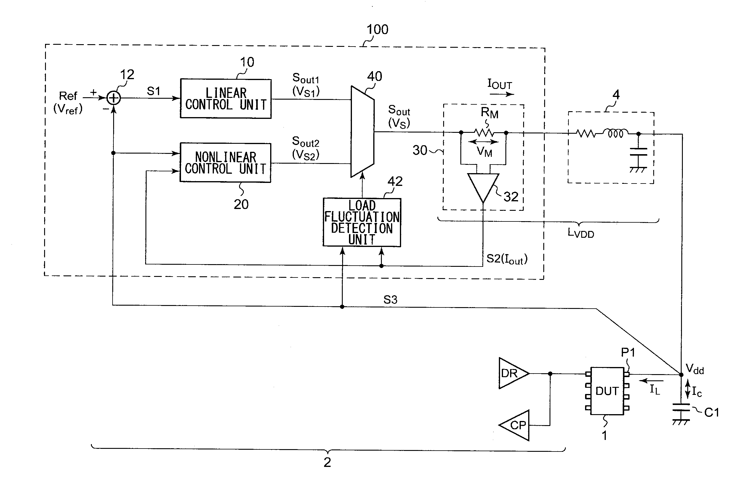
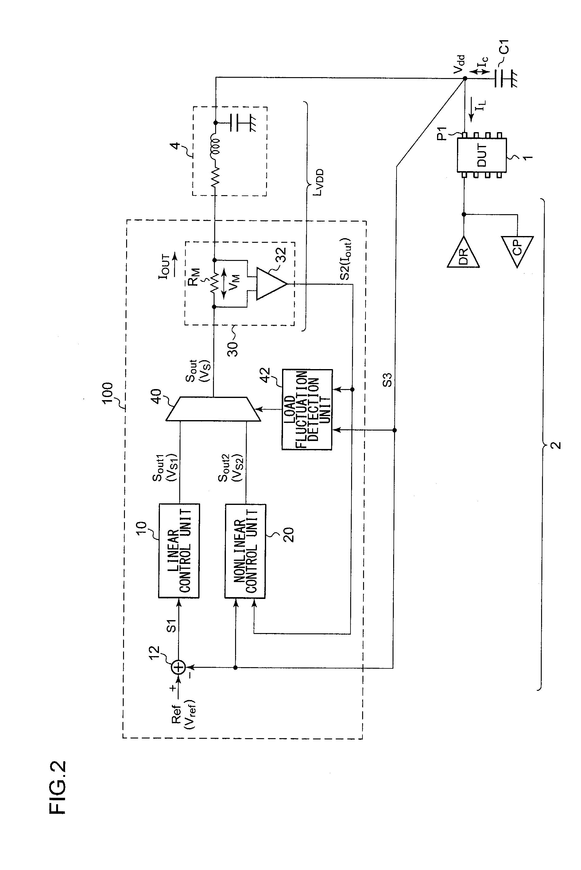
[0014]With such an embodiment, the amount of charge with which the capacitor is charged and the amount of charge with which the capacitor is discharged are appropriately calculated, and the output amount is controlled such that the amount of charge with which the capacitor is charged (discharged) in the first period matches the amount of charge with which the capacitor is discharged (charged) in the second period. Thus, such an arrangement is capable of suppressing fluctuation in the power supply voltage, or provides a reduction in the period of time required to stabilize fluctuation in the power supply voltage. Alternatively, such an arrangement is capable of providing an intentional change in the power supply voltage, and of controlling a period of time required to stabilize the power supply voltage as desired.
[0016]With such an embodiment, by switching the control operation between the linear control operation and the nonlinear control operation according to the state of the load, such an arrangement provides further stabilization of the power supply voltage.

Problems solved by technology

In addition, in a case in which the controller 1024 is designed giving consideration to the effects of the parasitic parameter 1030, such an arrangement leads to a complicated configuration and an increase in the number of circuit components, which is also a problem.

Method used


Image

  • Power supply apparatus
  • Power supply apparatus
  • Power supply apparatus

Examples


Embodiment Construction

[0030]The invention will now be described based on preferred embodiments which do not intend to limit the scope of the present invention but exemplify the invention. All of the features and the combinations thereof described in the embodiment are not necessarily essential to the invention.

[0031]In the present specification, the state represented by the phrase “the member A is connected to the member B” includes a state in which the member A is indirectly connected to the member B via another member that does not substantially affect the electric connection therebetween, or that does not damage the functions or effects of the connection therebetween, in addition to a state in which the member A is physically and directly connected to the member B.

[0032]Similarly, the state represented by the phrase “the member C is provided between the member A and the member B” includes a state in which the member A is indirectly connected to the member C, or the member B is indirectly connected to ...


PUM


Abstract

A load capacitor is connected to a power supply terminal of a DUT. A current detection unit detects an output current output from a power supply apparatus. A nonlinear control unit controls its output amount so as to provide a balance between an amount of charge with which the load capacitor is charged or discharged in a first period, from a first timing at which a change occurs in a load current that flows into the power supply terminal of the DUT until a second timing at which the load current matches the output current, and an amount of charge with which the load capacitor is charged or discharged in a second period, from the second timing until a third timing at which the control operation ends.

Description

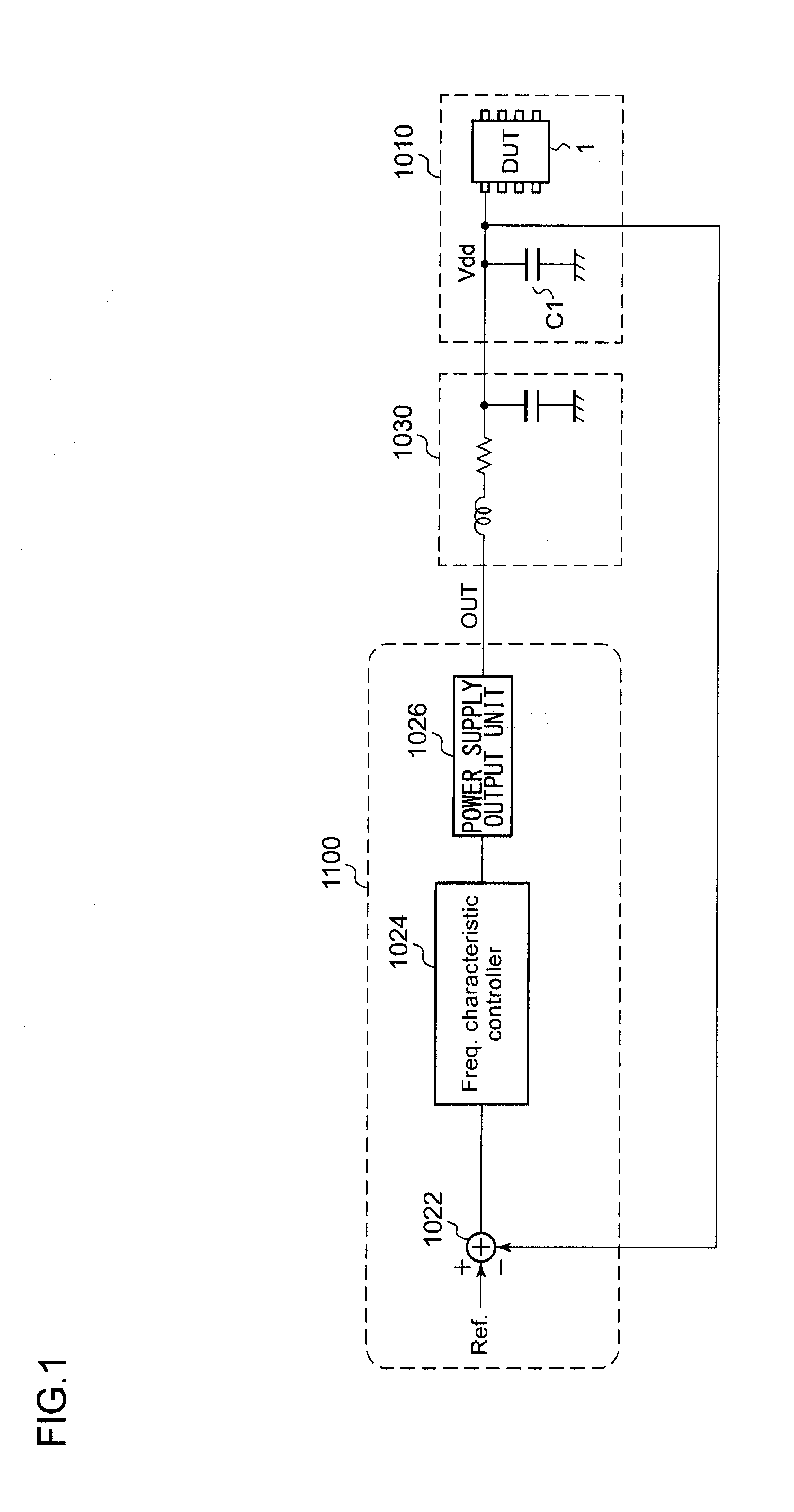
BACKGROUND OF THE INVENTION[0001]1. Field of the Invention[0002]The present invention relates to a power supply apparatus configured to supply electric power to a semiconductor device.[0003]2. Description of the Related Art[0004]A test apparatus includes a power supply apparatus configured to supply a power supply voltage or power supply current (which will be referred to as the “power supply voltage Vdd” hereafter) to a device under test (DUT). FIG. 1 is a block diagram which shows a schematic configuration of a conventional power supply apparatus. A power supply apparatus 1100 includes a power supply output unit 1026 and a frequency controller (which will be referred to as the “controller” hereafter) 1024 configured to control the power supply output unit 1026. For example, the power supply output unit 1026 is configured as an operational amplifier (buffer), a DC / DC converter, a linear regulator, or a constant current source, and is configured to generate a power supply voltage or...

Claims


Application Information

Patent Timeline
IPC IPC(8): G05F1/46
CPCG01R31/40H02M3/156H02M3/1566G05F1/10G05F1/565
Inventor SHIMIZU, TAKAHIKODEGAWA, KATSUHIKO
Owner ADVANTEST CORP
Learn More