Phased array antenna and its phase calibration method

Active Publication Date: 2012-06-14
DENSO CORP
View PDF43 Cites 19 Cited by
  • Summary
  • Abstract
  • Description
  • Claims
  • Application Information

AI Technical Summary

Benefits of technology

[0034]According to the phase calibration method, side lobes in

Problems solved by technology

However, it is difficult to accurately calibrate the phased array antenna configured to reduce side lobes of the phased array antenna by gradually lowering the o

Method used


Image

  • Phased array antenna and its phase calibration method
  • Phased array antenna and its phase calibration method
  • Phased array antenna and its phase calibration method

Examples


Example

[0045]With reference to the accompanying drawings, hereinafter is described a phased array antenna and its calibration method according to an exemplary embodiment of the present invention.

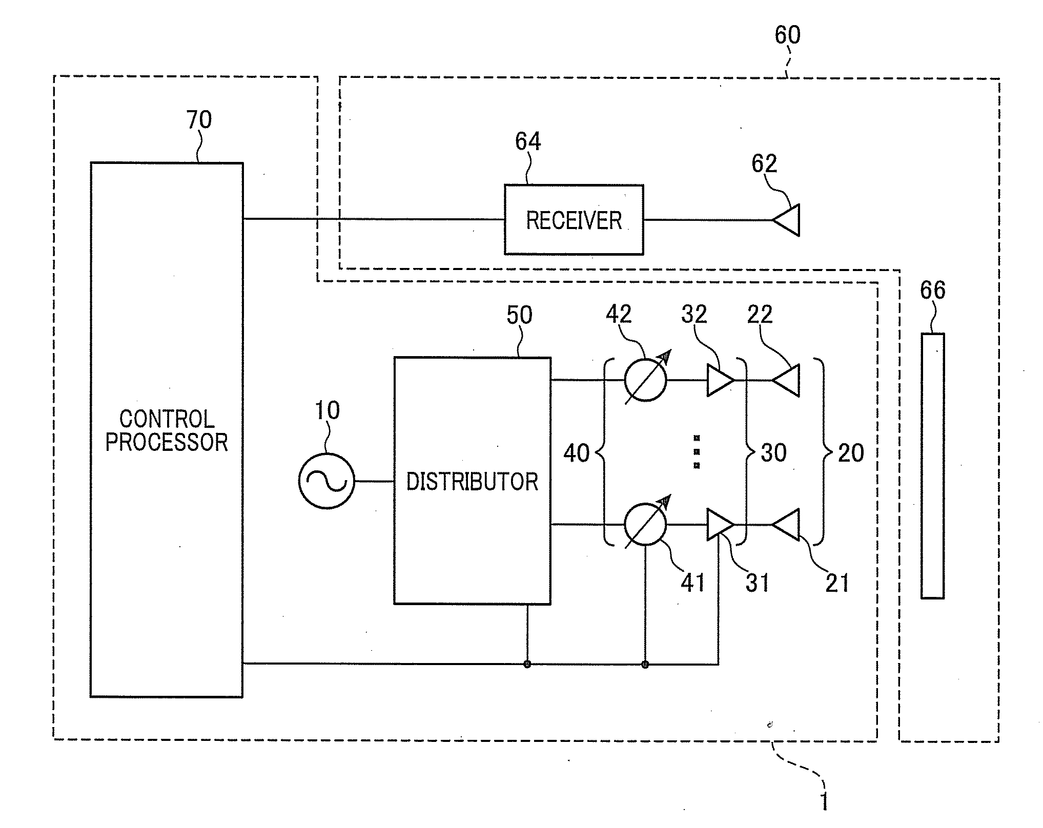
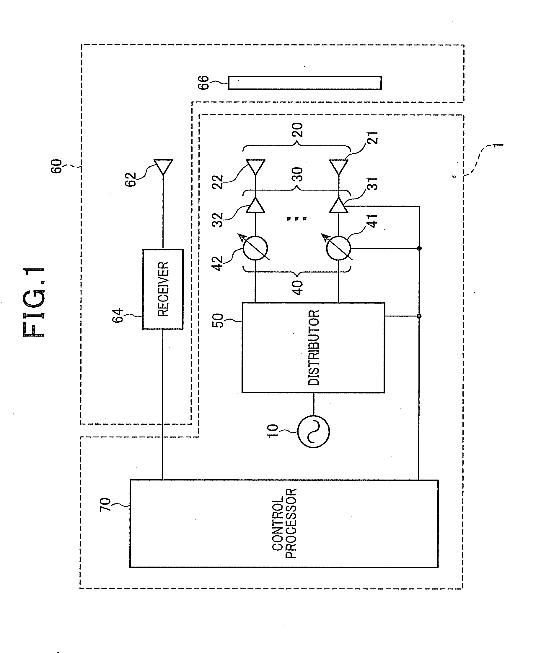
[0046]FIG. 1 is a schematic block diagram illustrating a configuration of a phased array antenna 1 according to the exemplary embodiment. The phased array antenna 1 can be applied to a radar apparatus such as an on-board radar mounted on a vehicle. A shown in FIG. 1, the phased array antenna includes an oscillator 10, a plurality of transmitting antenna elements 20 (hereinafter referred to as “antenna elements”), an amplifier 30, a phase shifter 40, a distributor 50, and a control processor 70.

[0047]Additionally, a received power detector 60 (corresponding to a “receiving unit” according to the exemplary embodiment of the present invention) is arranged to detect a radiated power of radio waves outputted by the phased array antenna 1.

[0048]The oscillator 10 is a device that generates radio waves, an...


PUM


Abstract

A phased array antenna includes an oscillator, a plurality of antenna elements, a phase shifter, a distributor, a receiver, and a control processor. The control processor performs a first calibration process to calibrate a phase of the phase shifter connected to a pair of antenna elements that is selected from the antenna elements and are located at a pair of positions symmetric with respect to a central axis of an array formed by the phased array antenna, and a second calibration process to calibrate a phase of the phase shifter connected to a pair of target antenna elements with respect to a phase of the phase shifter connected to a reference antenna elements located at a central portion of the array. The pair of target antenna elements are located at a pair of positions that are symmetric with respect to the central axis of the array.

Description

CROSS-REFERENCE TO RELATED APPLICATION[0001]This application is based on and claims the benefit of priority from earlier Japanese Patent Application No. 2010-274512 filed Dec. 9, 2010, the description of which is incorporated herein by reference.BACKGROUND OF THE INVENTION[0002]1. Technical Field of the Invention[0003]The present invention relates to a phased array antenna including a plurality of antenna elements and its phase calibration method for calibrating a phase of the plurality of antenna elements.[0004]2. Related Art[0005]A phased array antenna including a plurality of antenna elements is needed to calibrate a phase of each antenna element in such a manner that radio waves outputted by the antenna elements have the same phase under a predetermined set of conditions.[0006]In the related art, a technique is known to, upon a calibration of a phase of the plurality of antenna elements, (i) change a phase of only one arbitrary antenna element under condition that radio waves wi...

Claims


Application Information

Patent Timeline
IPC IPC(8): H01Q3/00
CPCH01Q3/36H01Q3/267
Inventor OOKAWA, KUNIHIKO
Owner DENSO CORP
Why Eureka
Try Eureka