Phased array antenna and its phase calibration method

a phase calibration and array antenna technology, applied in antennas, instruments, wave based measurement systems, etc., can solve the problems of difficult to precisely obtain the correlation between the resultant change in this one antenna element and the radiated power, and the low radiated power that can be received at the receiver, so as to achieve easy and accurate calibration.

Active Publication Date: 2012-06-14
DENSO CORP
View PDF24 Cites 18 Cited by
  • Summary
  • Abstract
  • Description
  • Claims
  • Application Information

AI Technical Summary

Benefits of technology

[0030]According to the above phase calibration method, the phase of anten...

Problems solved by technology

However, in the case where only one antenna elements is changed, a radiated power capable of being received at the receiver is low.
This makes it difficult to precisely obtain a correlation between the resultant change in this one antenna element and t...

Method used


Image

  • Phased array antenna and its phase calibration method
  • Phased array antenna and its phase calibration method
  • Phased array antenna and its phase calibration method

Examples


first embodiment

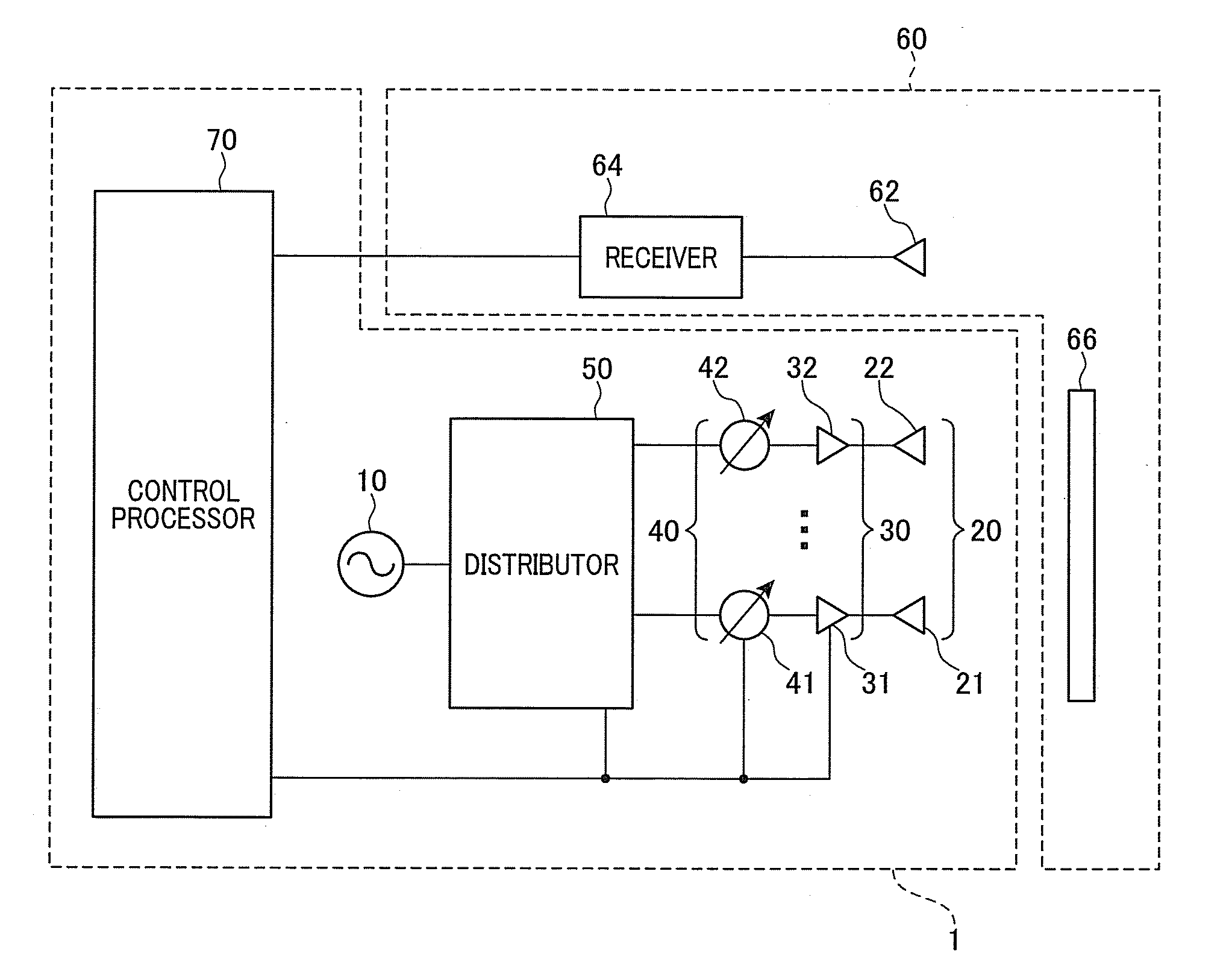
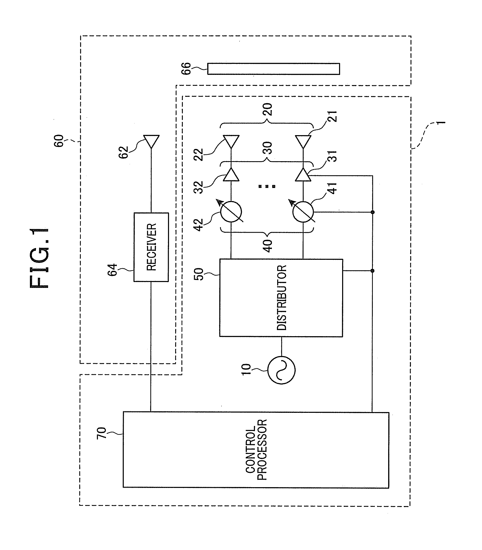
[0038]FIG. 1 is a schematic block diagram illustrating a configuration of a phased array antenna 1 according to a first exemplary embodiment. The phased array antenna 1 can be applied to a radar apparatus such as an on-board radar mounted on a vehicle. A shown in FIG. 1, the phased array antenna includes an oscillator 10, a plurality of transmitting antenna elements 20 (hereinafter referred to as “antenna elements”), an amplifier 30, a phase shifter 40, a distributor 50, and a control processor 70.

[0039]Additionally, a received power detector 60 (corresponding to a “receiving unit” according to the exemplary embodiment of the present invention) is arranged to detect a radiated power of radio waves outputted by the phased array antenna 1.

[0040]The oscillator 10 is a device that generates radio waves, and outputs a high-frequency (radio-frequency) signal oscillated by e.g., a Klystron, a travelling-wave tube, a magnetron, a Gunn diode as radio wave with stable frequency of several gig...

second embodiment

[0071]Next, the phased array antenna 1 according to a second exemplary embodiment that is different from the above first embodiment in a selection of the reference antenna element 21 and the target antenna element 22 is described.

[0072]In the phased array antenna 1 according to the present embodiment, the components identical with or similar to those in the phased array antenna 1 according to the first embodiment are given the same reference numerals for the sake of omitting unnecessary explanation.

[0073]In the control processor 70 of the phased array antenna 1, the CPU reads a program stored in the ROM and then executes the following calibration process.

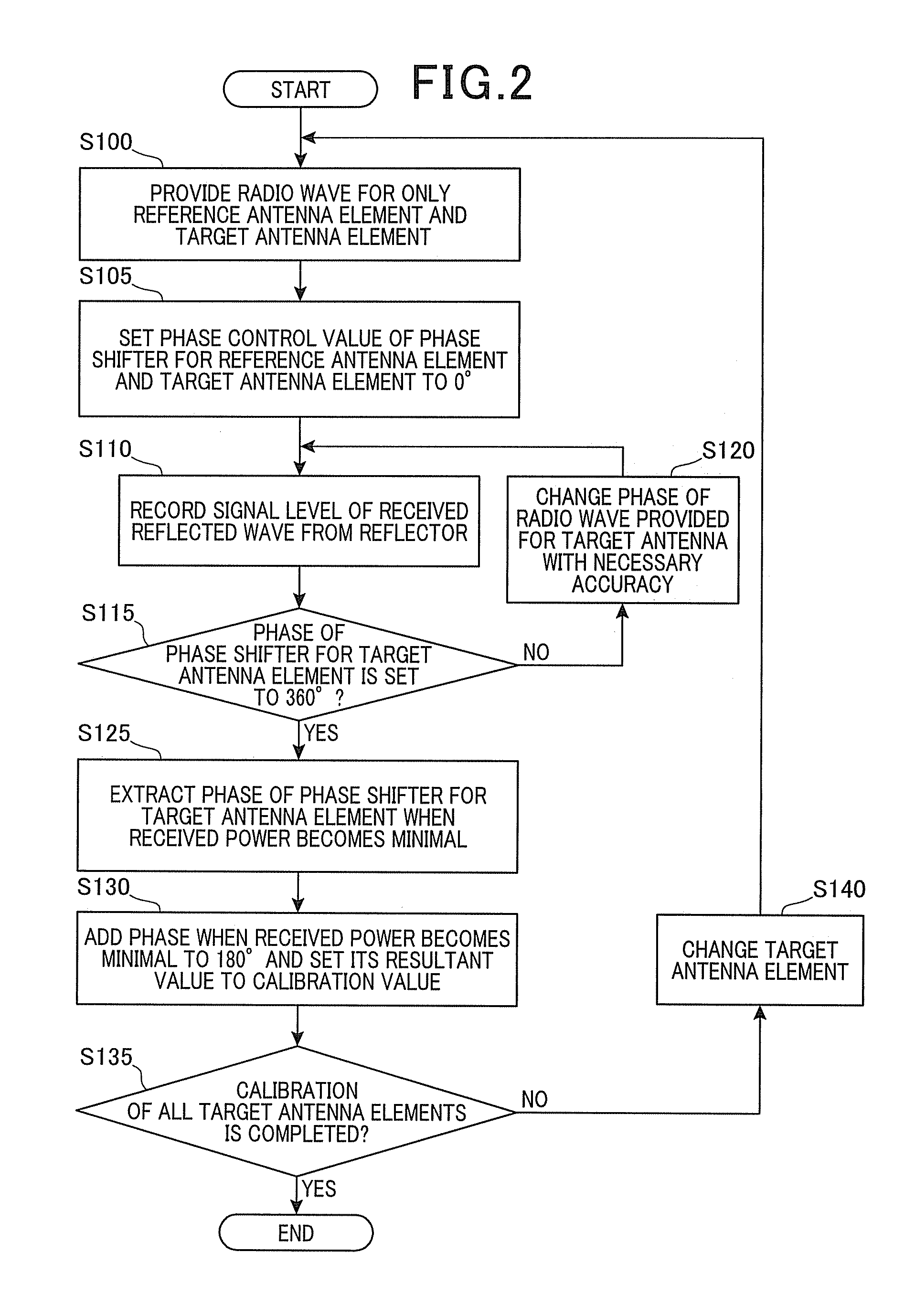
[0074]FIG. 4 shows a flow of a calibration process performed by the CPU of the control processor 70 according to the present embodiment.

[0075]In the calibration process, first, at step S100, the CPU performs a process to provide only a reference antenna element 21 to be reference of a phase calibration of all of the antenna elements...


PUM


Abstract

A phase array antenna includes an oscillator, a plurality of antenna elements, a phase shifter, a distributor, a receiving unit, and a control processor. The control processor performs a calibration process to select, from the antenna elements, a reference and target antenna elements to allow the radio waves generated by the oscillator to be provided for the reference and target antenna elements via the distributer, obtain a pattern of a change in a received power of radio waves received at the receiving unit, when a phase of the phase shifter for the reference antenna element is fixed and a phase of the phase shifter for the target antenna element is changed, extract, from the pattern obtained, the phase of the phase shifter for the target antenna element at which the received power becomes a local minimal value, and add the phase extracted to 180° to set its resultant value to a calibration value for the phase of the phase shifter for the target antenna element.

Description

CROSS-REFERENCE TO RELATED APPLICATION[0001]This application is based on and claims the benefit of priority from earlier Japanese Patent Application No. 2010-274511 filed Dec. 9, 2010, the description of which is incorporated herein by reference.BACKGROUND OF THE INVENTION[0002]1. Technical Field of the Invention[0003]The present invention relates to a phased array antenna including a plurality of antenna elements and its phase calibration method for calibrating a phase of each antenna element.[0004]2. Related Art[0005]A phased array antenna including a plurality of antenna elements is needed to calibrate a phase of each antenna element in such a manner that radio waves outputted by the antenna elements have the same phase under a predetermined set of conditions.[0006]In the related art, a technique is known to, upon a calibration of a phase of the plurality of antenna elements, (i) change a phase of only one arbitrary antenna element under condition that radio waves with a predeter...

Claims


Application Information

Patent Timeline
IPC IPC(8): G01S7/40
CPCG01S7/4004G01S7/40H01Q3/36H01Q3/267
Inventor OOKAWA, KUNIHIKO
Owner DENSO CORP
Why Eureka
Try Eureka