

Cartridge and method for manufacturing the same
a cartridge and cartridge technology, applied in the field of cartridges, can solve the problems of difficult to expel air bubbles into the liquid detection chamber, change the position of the film, and reduce the detection accuracy of the state of remaining liquid by the liquid detector, so as to achieve the effect of reducing the structure of the cartridge and efficiently laying ou
- Summary
- Abstract
- Description
- Claims
- Application Information
AI Technical Summary
Benefits of technology
Problems solved by technology
Method used
Image

Examples
modification 1
[0111
[0112]In the ink detector 84 of the cartridge 40 according to the embodiment described above, the cutout 107 of the spring-receiving element 103 is formed by cutting out the whole height of the spring-receiving element 103 to the upper surface (surface abutting the film 106). It is, however, not necessary to cut out the whole height of the spring-receiving element 103 to its upper surface, as long as the cutout of the light-receiving element 103 can form a space, through which air bubbles pass. For example, a cutout 107b may be provided only in the side face (side wall) extended downward from the upper surface of the spring-receiving element 103.
[0113]FIG. 18 illustrates inside of the ink detector 84b according to one modification. In the ink detector 84b according to this modification, the thickness of the spring-receiving element 103 shown in FIG. 18 is made greater than the thickness of the spring-receiving element 103 shown in FIGS. 7 and 8. The spring-receiving element 103...
modification 2
[0115
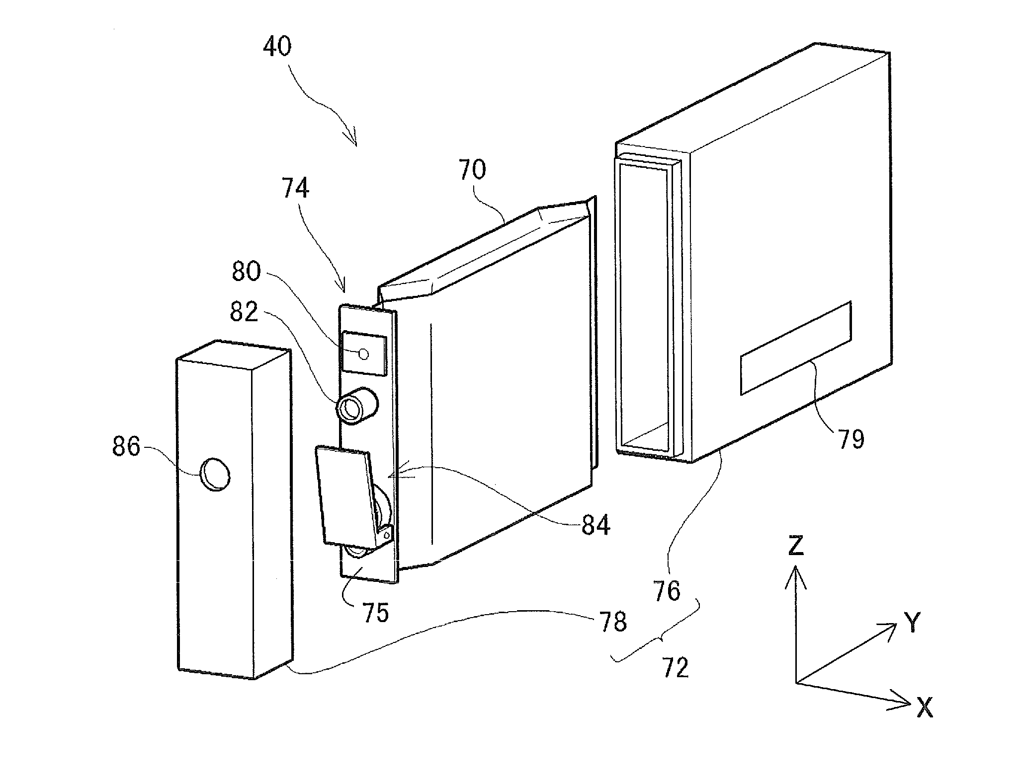
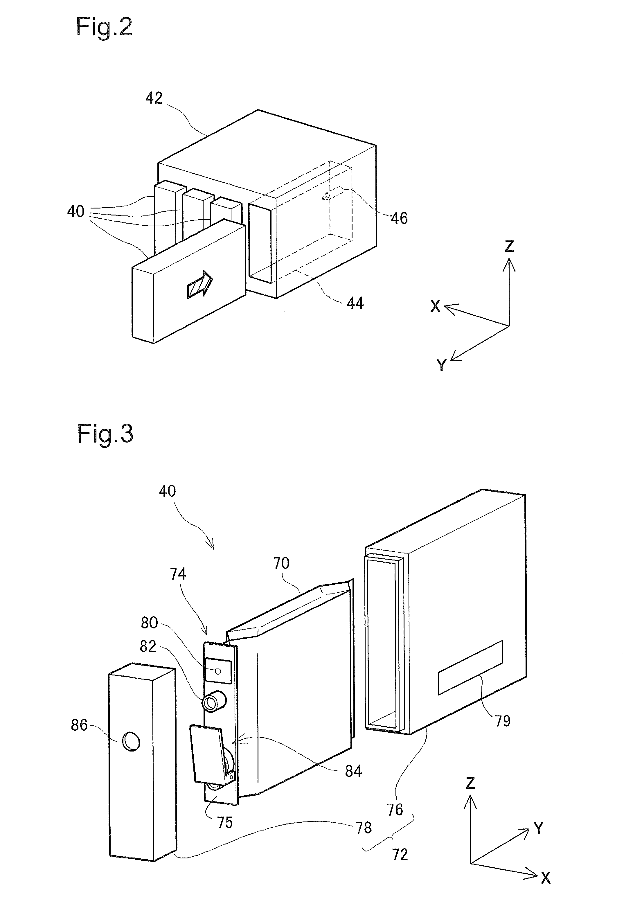
[0116]According to the embodiment described above, the ink pack 70 is directly fixed (welded) to the ink supply member 74. According to one modification, the ink supply member 74 and the ink pack 70 may be interconnected by means of a flow path member, such as a tube. In this modification, the main body casing 76 may be omitted according to the requirements.
modification 3
[0117
[0118]According to the embodiment described above, the ink filler port 80, the ink supply port 82, the ink detector 84 and the connection port 92 are provided along the longitudinal direction on the surface 75 of the ink supply member 74. According to one modification, two or more of these elements may be provided in a direction orthogonal to the longitudinal direction. More specifically, for example, the ink filler port 80 and the ink supply port 82 may be arranged to be aligned in the direction orthogonal to the longitudinal direction. The ink filler port 80, the ink supply port 82, the ink detector 84 and the connection port 92 are arranged in a line according to the above embodiment, but may be arranged in zigzag or may be arranged at discrete positions with different intervals from a straight line parallel to the longitudinal direction.
PUM
| Property | Measurement | Unit |
|---|---|---|
| angle | aaaaa | aaaaa |
| angle | aaaaa | aaaaa |
| angle | aaaaa | aaaaa |
Abstract
Description
Claims
Application Information