
Heat dissipation system

a heat dissipation system and heat dissipation technology, applied in the direction of cooling/ventilation/heating modifications, electrical apparatus casings/cabinets/drawers, instruments, etc., can solve the problem of ineffective heat dissipation

Inactive Publication Date: 2012-06-14
HONG FU JIN PRECISION IND (SHENZHEN) CO LTD +1
View PDF5 Cites 8 Cited by
  • Summary
  • Abstract
  • Description
  • Claims
  • Application Information

AI Technical Summary

Benefits of technology

[0002]The disclosure generally relates to a heat dissipation system, and especially to a heat dissipation system for improving heat dissipation efficiency of a mass storage device in computer system.

Problems solved by technology

However, the typical SFF heat dissipation system uses an axial flow CPU fan to dissipate heat for the CPU.
The heated airflow tends to be reflected by other components and causes interference in the computer case, which has an influence on mass storage devices so heat dissipation is not efficient.

Method used


Image

  • Heat dissipation system
  • Heat dissipation system
  • Heat dissipation system

Examples


Embodiment Construction

[0010]The disclosure is illustrated by way of example and not by way of limitation in the figures of the accompanying drawings in which like references indicate similar elements. It should be noted that references to “an” or “one” embodiment in this disclosure are not necessarily to the same embodiment, and such references mean at least one.

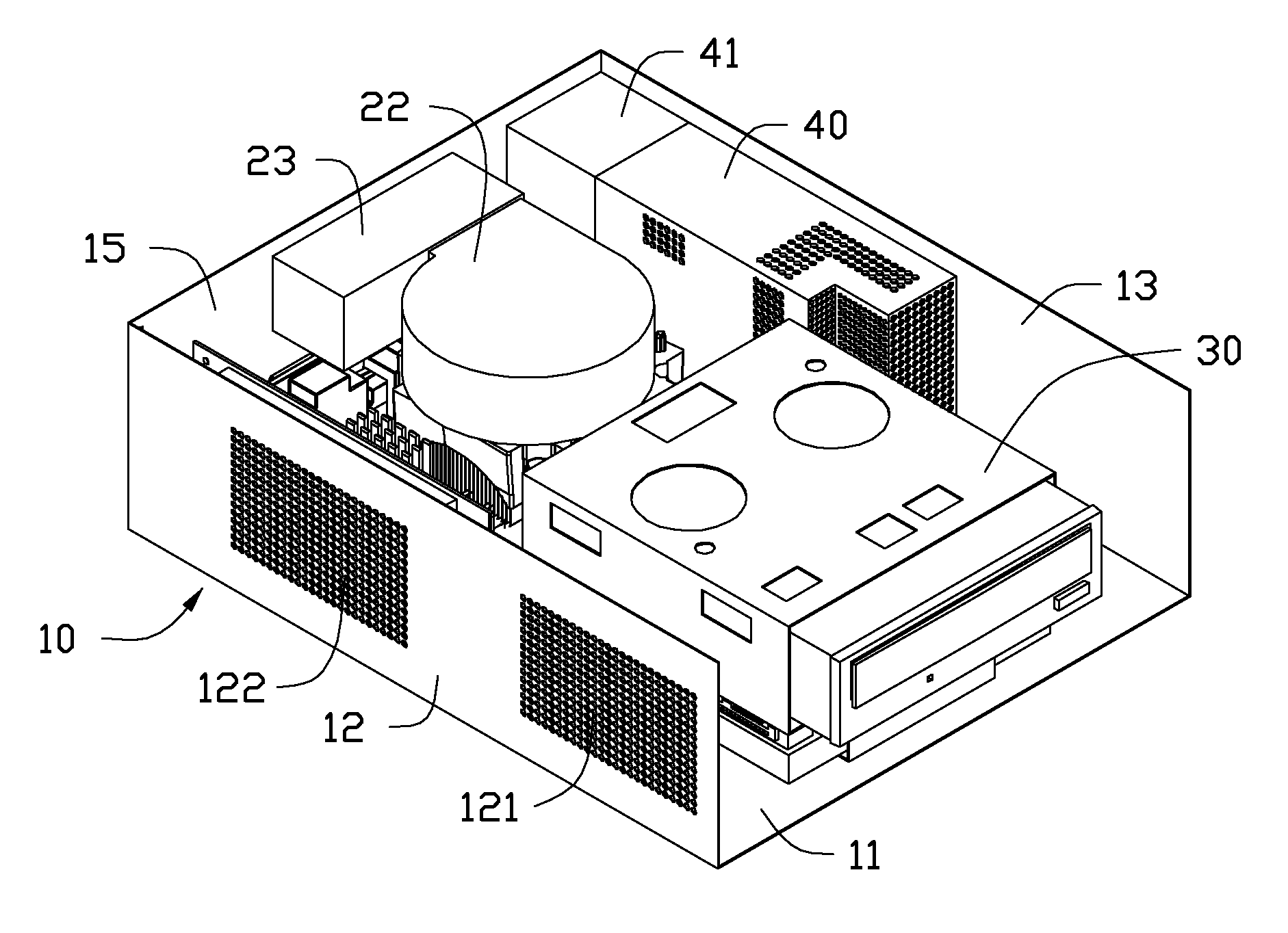
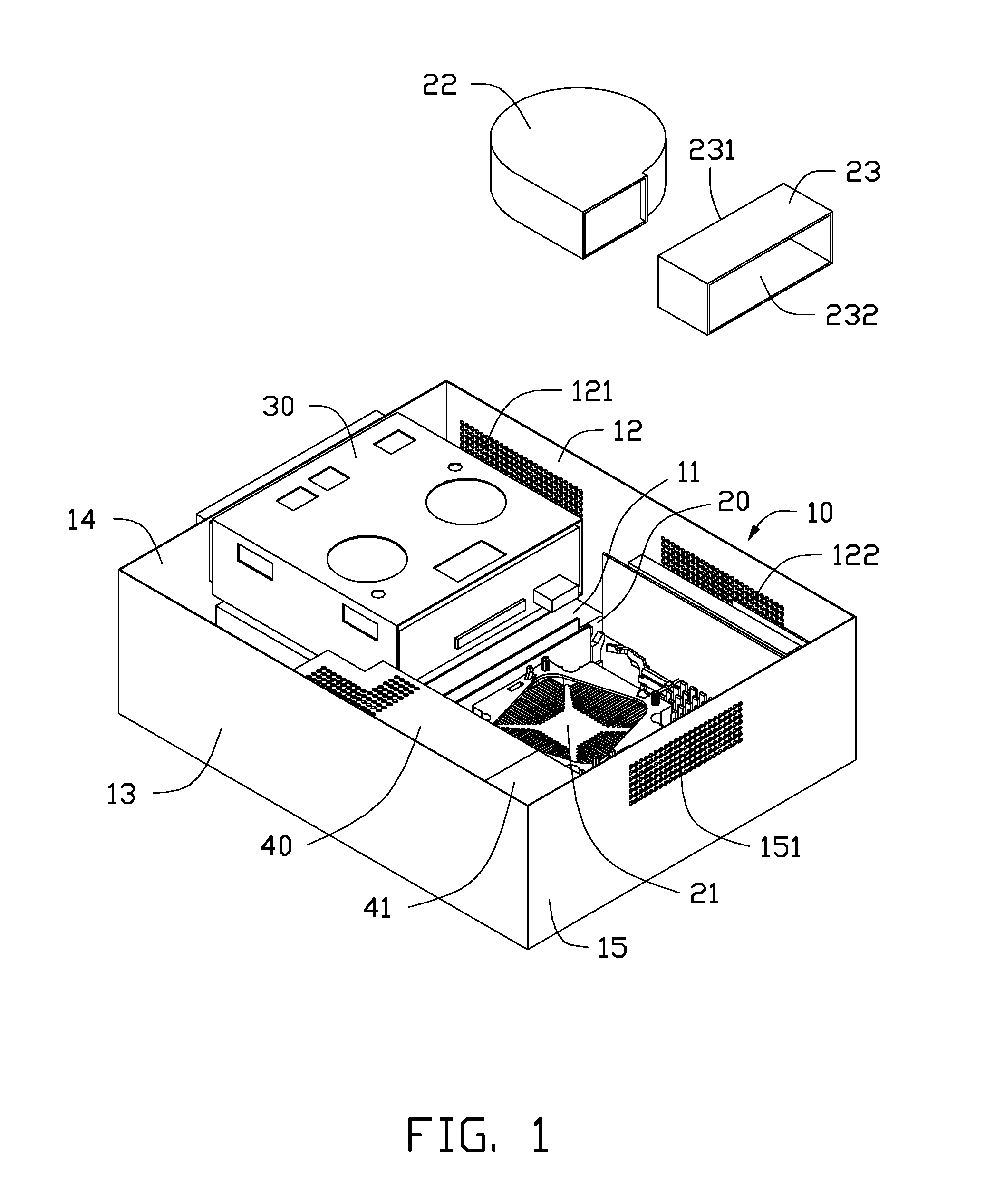
[0011]Referring to FIG. 1, an embodiment of a heat dissipation system includes a computer case 10. The computer case 10 includes a base plate 11, a first side plate 12, a second side plate 13, a front plate 14 and a back plate 15. The first side plate 12, the second side plate 13, the front plate 14 and the back plate 15 are perpendicular to the base plate 11.

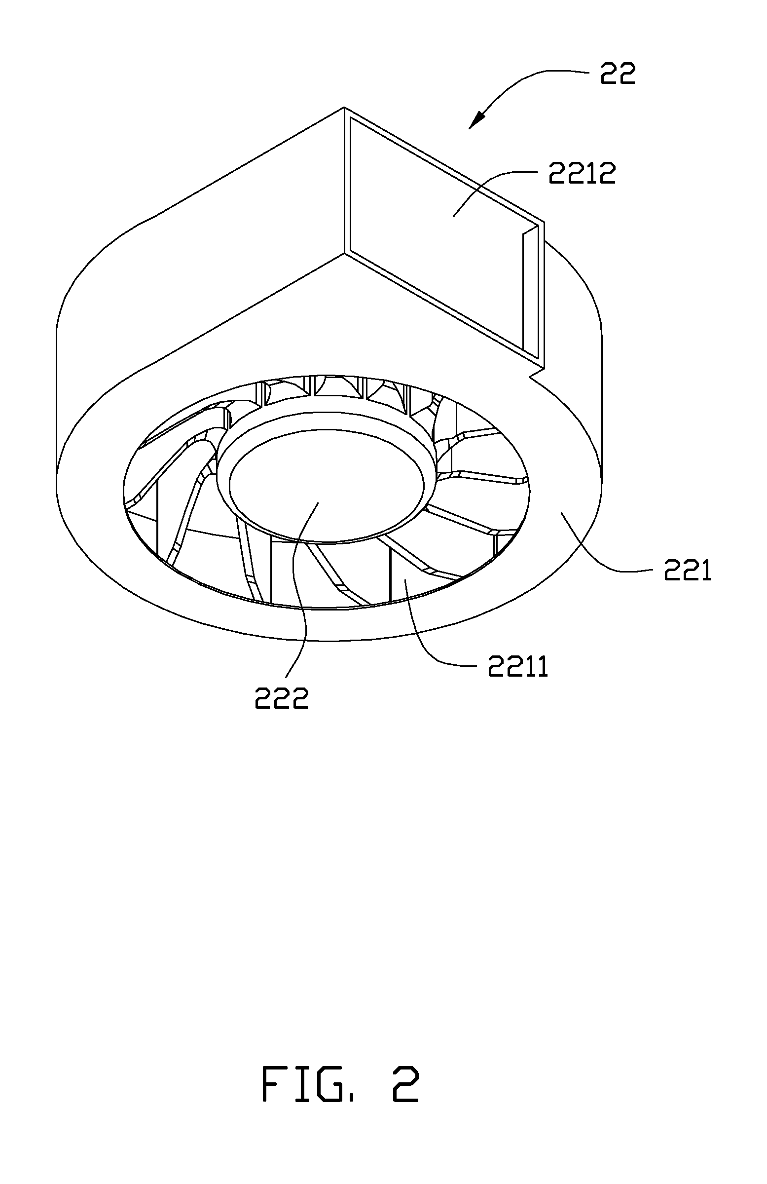
[0012]The base plate 11 includes a motherboard 20 positioned thereon adjacent to the back plate 15. The motherboard 20 includes a heat sink 21 mounted thereon and a first fan 22 positioned on the heat sink 21. The base plate 11 includes a mass storage device 30 positioned beside the motherbo...


PUM


Abstract

A heat dissipation system includes a computer case having a base plate and a back plate perpendicularly to the base plate, a motherboard on the base plate adjacent to the back plate, and a mass storage device beside the motherboard. The motherboard has a heat sink and a first fan on the heat sink. The base plate has a second fan beside the motherboard. The second fan is adjacent to the back plate. The mass storage device is away from the back plate. The first fan rotates in such a manner that airflow is drawn into the computer case, flows through the heat sink and is exhausted out of the computer case. The second fan rotates in such a manner that airflow is drawn into the computer case, flows through the mass storage device and is exhausted out of the computer case.

Description

BACKGROUND[0001]1. Technical Field[0002]The disclosure generally relates to a heat dissipation system, and especially to a heat dissipation system for improving heat dissipation efficiency of a mass storage device in computer system.[0003]2. Description of Related Art[0004]A small form factor (SFF) is a computer form factor designed to minimize the spatial volume of a desktop computer. A typical SFF includes a CPU fan and a system fan in a computer case. A plurality of mass storage devices (hard disc driver, optical disc driver) is positioned in the computer case. A heat sink is mounted on the CPU to remove heat, and the CPU fan is fixed on the heat sink to blow airflow through the heat sink. The temperature of the airflow increases by the heat generated by the CPU as it passes through the heat sink. The heated airflow is then exhausted from the computer case by the system fan. However, the typical SFF heat dissipation system uses an axial flow CPU fan to dissipate heat for the CPU....

Claims


Application Information

Patent Timeline
IPC IPC(8): H05K7/20
CPCG06F1/20
Inventor CHEN, CHENSUN, HONG-ZHILI, YANG
Owner HONG FU JIN PRECISION IND (SHENZHEN) CO LTD
Learn More