Undershot Sluice Gate

Inactive Publication Date: 2012-06-14
RUBICON RES PTY LTD
View PDF4 Cites 6 Cited by
  • Summary
  • Abstract
  • Description
  • Claims
  • Application Information

AI Technical Summary

Benefits of technology

[0009]In a practical embodiment each liquid entry inlet includes a filter to reduce fluctuations in measurements due to impurities entering said sensors. The sensors may include a vertically disposed chamber to allow for ultrasonic measurement of liquid height in said chamber. The chambers are located on the outer opposing faces of said gate leaf or located inside said gate leaf adjacent the opposing faces of said gate leaf.
[0010]In a further aspect of the invention there is provided an undershot sluice gate to control flow of liquid th

Problems solved by technology

This problem has existed for over a century—the science of measuring flow through an undershot sluice gate is well established, but has been limited by th

Method used


Image

  • Undershot Sluice Gate
  • Undershot Sluice Gate
  • Undershot Sluice Gate

Examples


Embodiment Construction

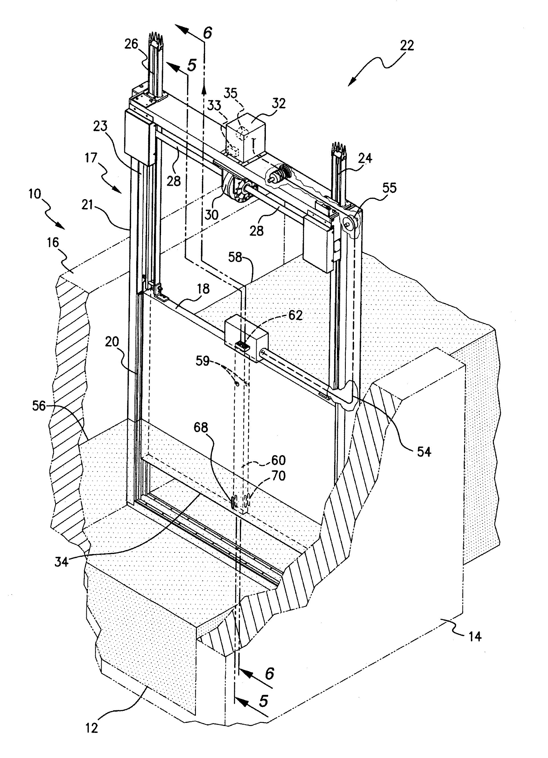
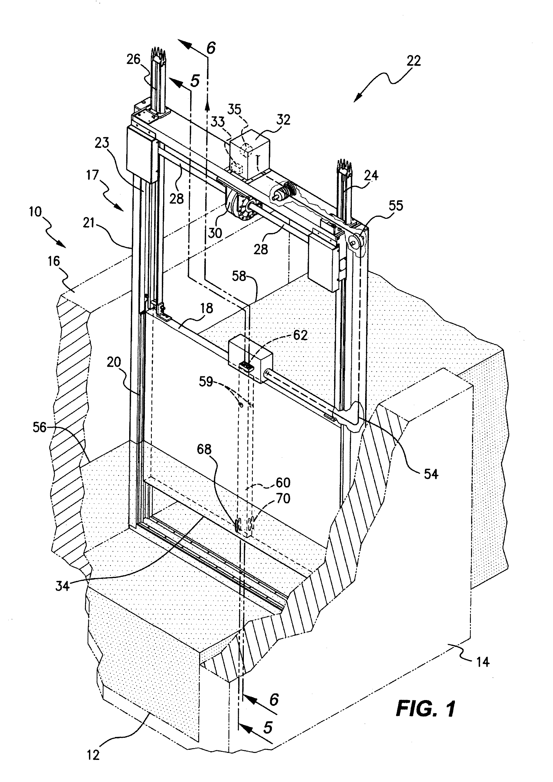
[0029]In FIGS. 1 to 8 of the drawings there is shown an irrigation channel 10 having a floor 12 and sides 14, 16. The irrigation channel 10 is typically for delivery of water for agriculture but the channel can be used for other purposes where flow control of water is required. A control gate 17 allows a controlled flow of water therethrough. The control gate 17 includes a gate leaf 18 which slides within a frame 20. Frame 20 has an outer frame 21 which is permanently secured to floor 12 and sides 14, 16 of irrigation channel 10 and a constraining frame 23 which slides within outer frame 21. The constraining frame 23 may be connected to and separated from the mating frame with no requirement to undertake civil works on the floor 12 and sides 14, 16 of the irrigation channel 10. Alignment holes 25 can be provided to provide correct alignment by insertion of location pins (not shown). This type of internal / external frame mechanism is further detailed in the specification of Internatio...


PUM


Abstract

The invention provides an undershot sluice gate (17) to control flow of liquid through an open channel (10). The gate (17) includes a gate leaf (18) adapted to be raised and lowered by a control means (22) to allow flow of liquid along open channel (10). Gate leaf (18) has at least a pair of opposing liquid level sensors (44, 46) on, or in, gate leaf (18) to provide measurement of liquid level upstream and downstream of gate leaf (18). The sensors (44, 46) are located at a predetermined distance from the lowermost edge of gate leaf (18) to allow said measurements without disturbance from the fluid flow profile resulting from movement of liquid beneath the lowermost edge of gate leaf (18).

Description

CLAIM OF PRIORITY[0001]This application is a continuation of and incorporates by reference International Application No. PCT / AU2010 / 000115, filed Feb. 5, 2010 and published as WO 2010 / 088731 A1 and A9 on Aug. 12, 2010, entitled “Undershot Sluice Gate”, which claims priority to Australian Patent Application Ser. No. 2009900439, filed Feb. 5, 2009.FIELD OF THE INVENTION[0002]This invention relates to an undershot sluice gate and relates particularly, though not exclusively, to an undershot sluice gate for irrigation channels.DESCRIPTION OF THE PRIOR ART[0003]In irrigation systems measurement of water levels for the purpose of flow measurement through an undershot sluice gate is required. The solution has been to locate water level instrumentation at a sufficient distance upstream and downstream of the sluice gate such that they are outside the turbulent velocity influenced region of the fluid flow. This problem has existed for over a century—the science of measuring flow through an un...

Claims


Application Information

Patent Timeline
IPC IPC(8): E02B7/20
CPCE02B7/28
Inventor AUGHTON, DAVID JOHNPEARSON, DAMIEN
Owner RUBICON RES PTY LTD
Why Eureka
Try Eureka