Battery system
a battery and system technology, applied in secondary cells, cell components, instruments, etc., can solve the problems of degrading secondary batteries, abrupt increase in internal temperature, thermal runaway state, etc., and achieve the effect of accurate detection
- Summary
- Abstract
- Description
- Claims
- Application Information
AI Technical Summary
Benefits of technology
Problems solved by technology
Method used
Image


Examples
first embodiment
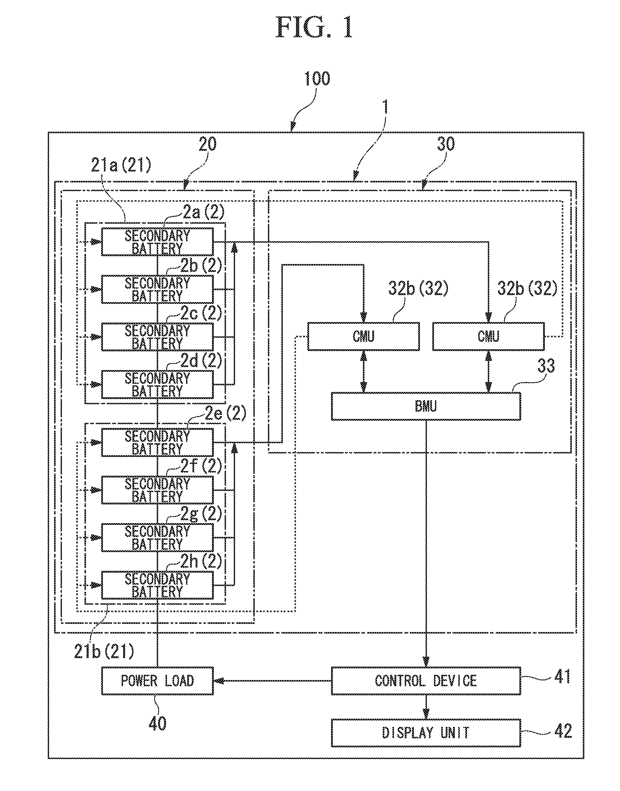
[0047]A first embodiment of the present invention will be described by referring to FIGS. 1 to 10. FIGS. 1 to 10 illustrate a battery system 1 of the first embodiment. As shown in FIG. 1, the battery system 1 of the embodiment includes: an assembled battery 20 which is formed by secondary batteries 2 corresponding to plural electrical cells and a BMS (Battery Management System) 30 which is a control unit monitoring and controlling the assembled battery 20. In the embodiment, the assembled battery 20 includes plural battery modules 21 which are formed by plural secondary batteries 2. Specifically, the assembled battery includes two battery modules 21a and 21b. Then, a battery module 21a is formed by four secondary batteries 2 (2a, 2b, 2c, and 2d). In the same way, the battery module 21b is formed by four secondary batteries 2 (2e, 2f, 2g, and 2h). Then, the assembled battery 20 is connected to a power load 40, and may be charged and discharged. Further, the BMS 30 is connected to a c...
second embodiment
[0070]Next, a second embodiment of the present invention will be described. FIGS. 12 to 19 illustrate the second embodiment of the present invention. Furthermore, in the embodiment, the same reference signs will be given to the same constituents as those of the above-described embodiment, and the description thereof will not be repeated.
[0071]As shown in FIGS. 12 and 13, in a battery system 60 of the embodiment, the battery accommodation casing 22 of the assembled battery 20 includes a partition plate 23 which divides the secondary batteries 2 inside the battery accommodation casing 22. Even in the embodiment, since the secondary batteries 2 are arranged according to the matrix of two by two, the partition plates 23 which divide the secondary batteries 2 are provided along the stacking direction X of the secondary battery 2 and the direction Y lying at right angles to the stacking direction X so as to intersect with each other at the center. Accordingly, in each secondary battery 2,...
third embodiment
[0080]Next, a third embodiment of the present invention will be described. FIGS. 20 to 23 illustrate the third embodiment of the present invention. Furthermore, in the embodiment, the same reference signs will be given to the same constituents as those of the above-described embodiment, and the description thereof will not be repeated.
[0081]As shown in FIGS. 20 and 21, in a battery system 70 of the embodiment, separation state detecting devices 71 further includes a light-transmissive member 72 which is installed between each of the first side surface 52 and the second side surface 54 of each secondary battery 2 and the battery accommodation casing partition plate wall surface 23a in addition to the light source 66, and the light amount detectors 67 and 68. The light-transmissive member 72 is a member which may elastically contract and expand, and is provided with a void 72a. In the embodiment, the void 72a corresponds to a penetration hole, and is formed along the optical path from...
PUM
 Abstract
Description
Claims
Application Information
 - R&D Engineer
- R&D Manager
- IP Professional
- Industry Leading Data Capabilities
- Powerful AI technology
- Patent DNA Extraction
Browse by: Latest US Patents, China's latest patents, Technical Efficacy Thesaurus, Application Domain, Technology Topic.
© 2024 PatSnap. All rights reserved.Legal|Privacy policy|Modern Slavery Act Transparency Statement|Sitemap