Printed circuit board connector

a technology of printed circuit board and connector, which is applied in the direction of coupling device connection, coupling/disconnecting parts engagement/disengagement, electrical apparatus, etc., can solve the problems of reduced space for mounting other electronic components, inability to ensure co-planarity of solder joint surfaces of the plurality of lead portions, and , so as to improve the mounting quality and uniform solder bonding thickness.

Active Publication Date: 2012-06-14
JST MFG CO LTD
View PDF5 Cites 10 Cited by
  • Summary
  • Abstract
  • Description
  • Claims
  • Application Information

AI Technical Summary

Benefits of technology

[0014]An object of the present invention is to provide a printed circuit board connector wherein solder-bonded surfaces of lead portions of contacts arranged in parallel in a

Problems solved by technology

However, in a plan view, this kind of reinforcing tab extends outward from the connector shell occupying a certain amount installation space on the printed circuit board.
This causes a problem of reduced space for mounting other electronic components.
For that reason, there is a problem that co-planarity cannot be ensured for the solder joint surfaces of the plurality of lead port

Method used


Image

  • Printed circuit board connector
  • Printed circuit board connector
  • Printed circuit board connector

Examples


first embodiment

Printed Circuit Board Connector Configuration

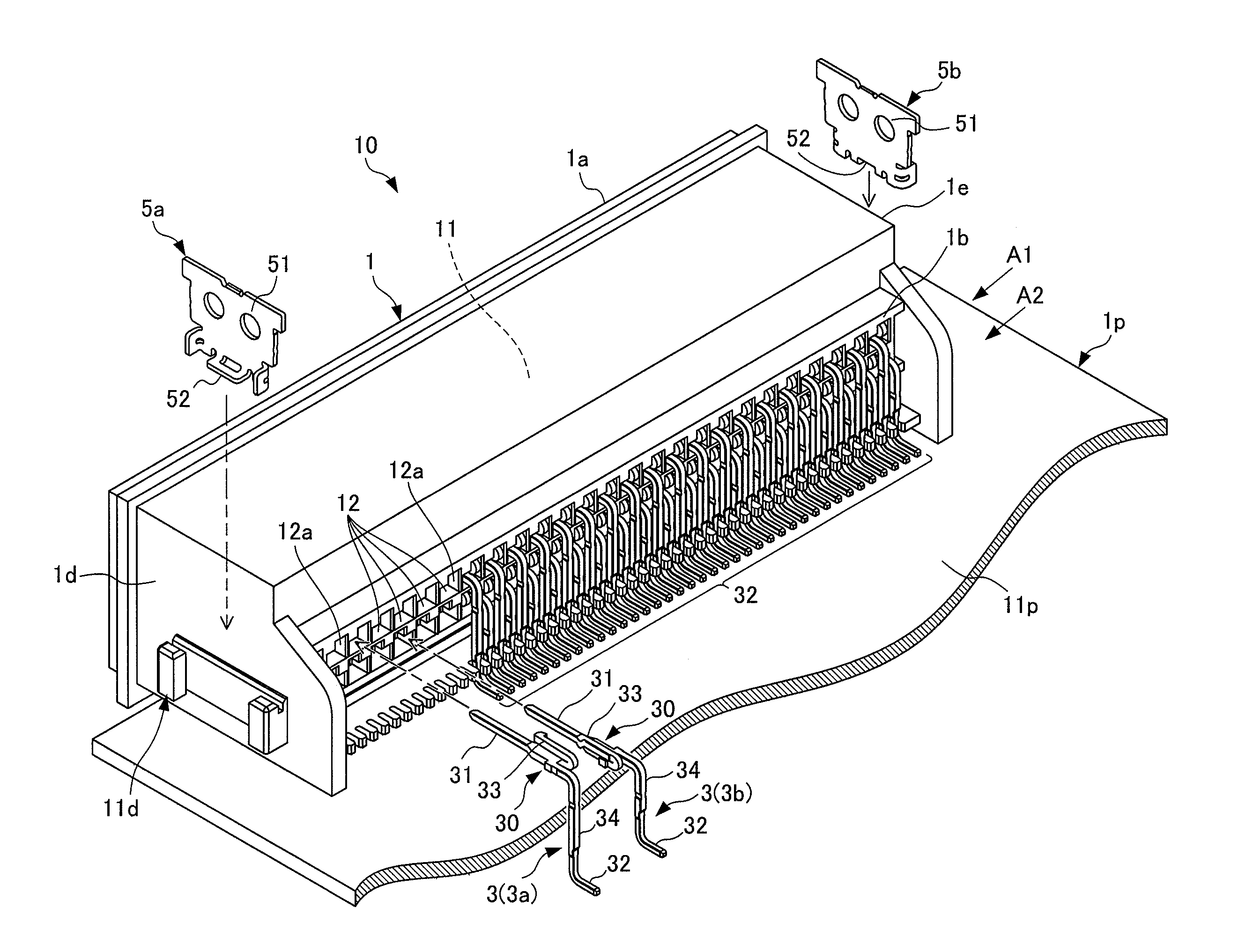
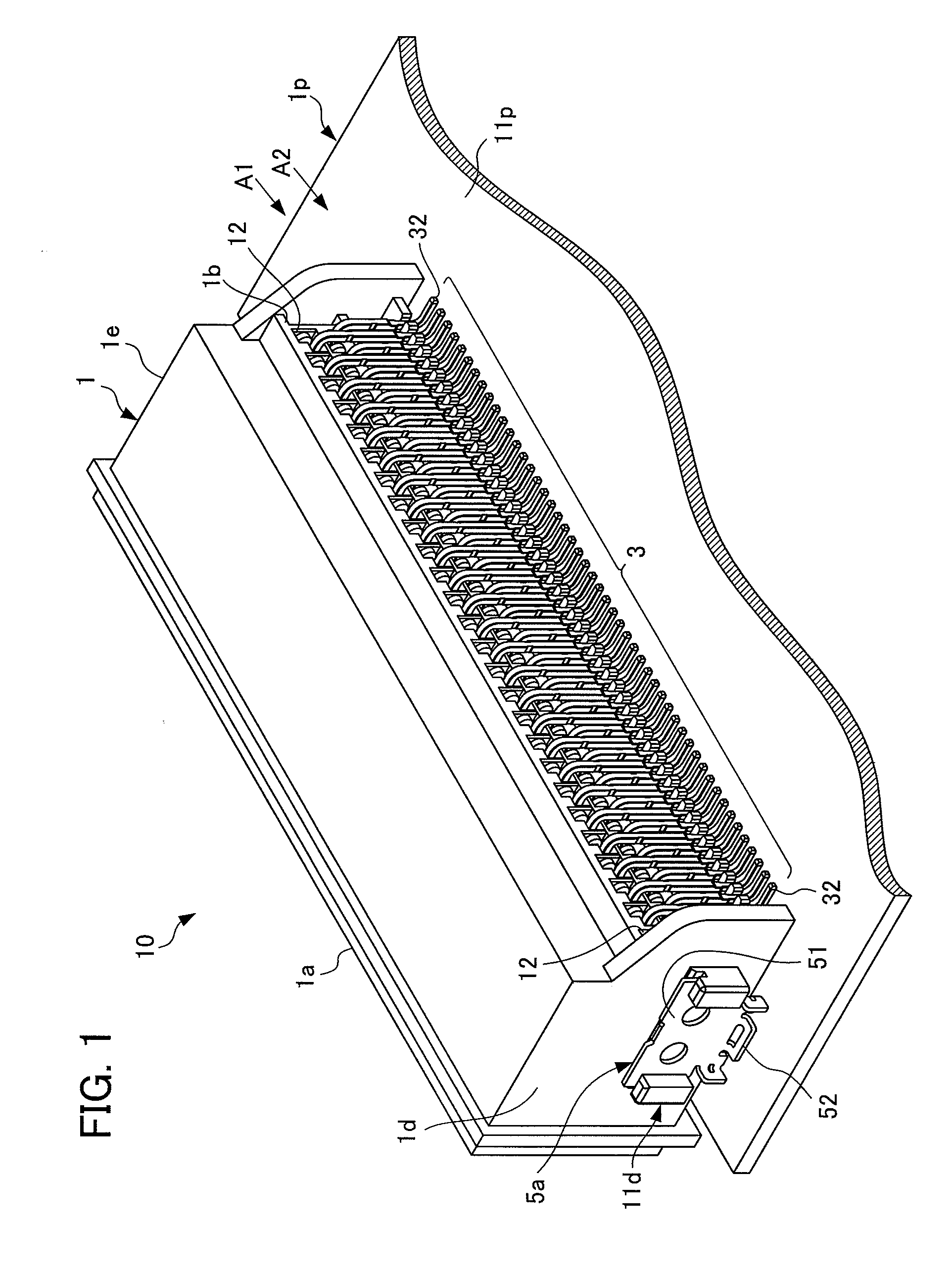
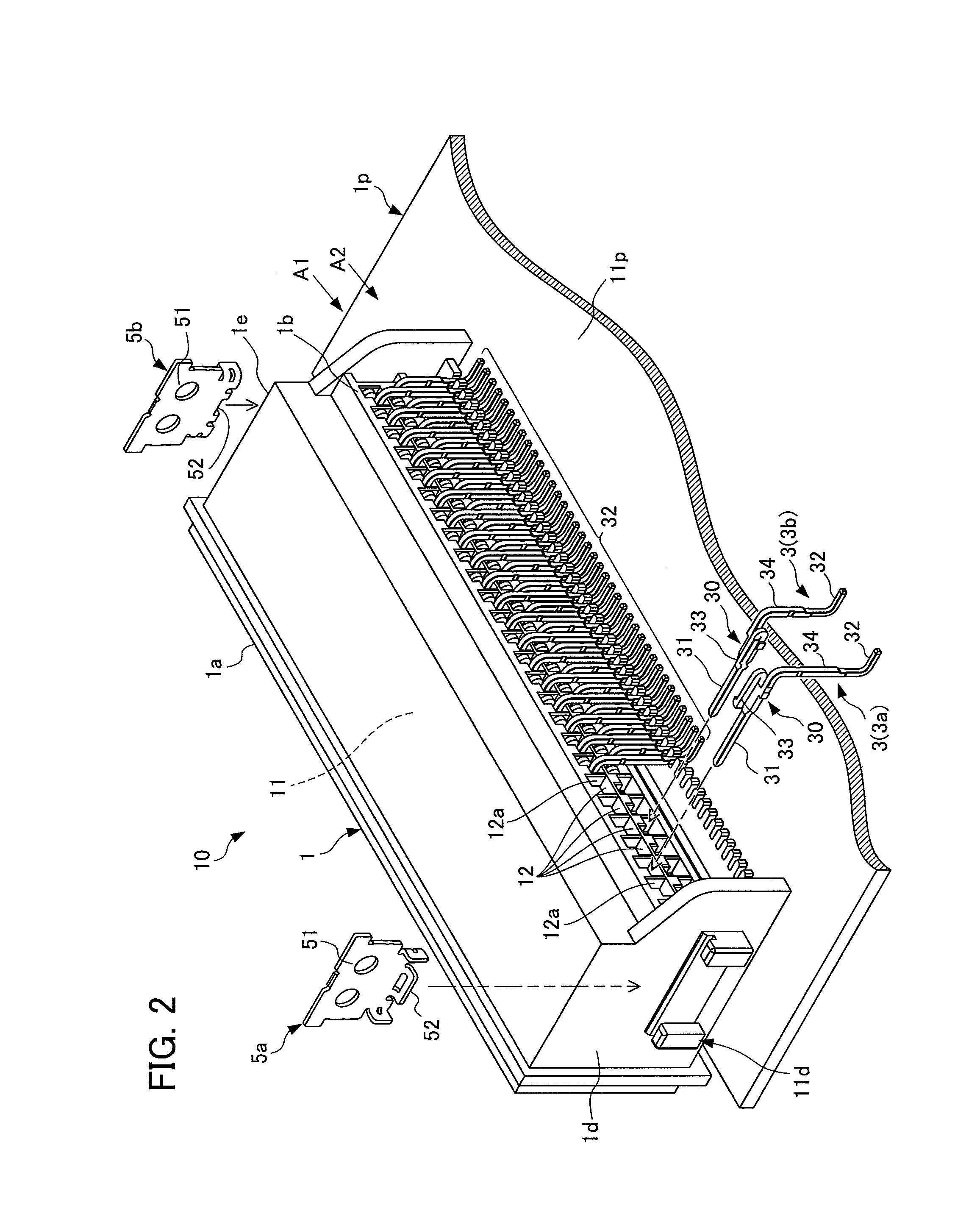
[0046]First, the printed circuit board connector configuration according the first embodiment of the present invention will be explained. FIG. 1 is a perspective view of a printed circuit board connector configuration according to the first embodiment of the present invention with the printed circuit board connector seen from a top surface side. FIG. 2 is an exploded perspective view of the printed circuit board connector configuration according to the first embodiment with the printed circuit board connector seen from a top surface side.

[0047]FIG. 3 is a perspective view of the printed circuit board connector configuration according to the first embodiment with the printed circuit board connector seen from a bottom surface side. FIG. 4 is a perspective view of the printed circuit board connector according to the first embodiment, showing a cross-section of the housing.

[0048]FIG. 5 is a plan view of the printed circuit board connector acc...

second embodiment

Printed Circuit Board Connector Configuration

[0067]The printed circuit board connector configuration according the second embodiment of the present invention will now be explained. FIG. 8 is a perspective view of a printed circuit board connector configuration according to the second embodiment of the present invention with the printed circuit board connector seen from a top surface side. FIG. 9 is an exploded perspective view of the printed circuit board connector configuration according to the second embodiment with the printed circuit board connector seen from a top surface side.

[0068]FIG. 10 is a perspective view of the printed circuit board connector configuration according to the second embodiment with the printed circuit board connector seen from a bottom surface side. FIG. 11 is a longitudinal section profile view of the printed circuit board connector according to the second embodiment cut along a first contact. FIG. 12 is an expanded longitudinal section profile view of an...


PUM


Abstract

A printed circuit board connector is equipped with a housing and plurality of contacts. The housing has an insertion chamber 11 inserted by the mating-side connector, and a plurality of contact-insertion holes inserted by the contacts. The contact has a base portion, a contact-connecting portion that connects with a mating-side contact, and a lead portion that is solder-bonded to the printed circuit board. The base portion and the housing have a contact lance and level that engage with each other so that the contact does not move in an insertion direction to the contact insertion hole or a reverse direction, and the contact lance and level swingably hold the base portion inside the contact-insertion hole so that the lead portion approaches and separates from the printed circuit board surface.

Description

[0001]This application is based on and claims the benefit of priority from Japanese Patent Application No. 2010-276567, filed on 13 Dec. 2010, the content of which is incorporated herein by reference.BACKGROUND OF THE INVENTION[0002]1. Field of the Invention[0003]The present invention relates to printed circuit board connectors. The present invention particularly relates to a printed circuit board connector structure to which a plurality of contact leads can be securely solder-bonded to a printed circuit board surface.[0004]2. Related Art[0005]A shell formed by a metallic plate composes an outer shell of a connector on a printed circuit board connector, for example. A part of the shell is solder-bonded to a surface of the printed circuit board as a reinforcing tab extending from the outer shell to improve connector strength.[0006]However, in a plan view, this kind of reinforcing tab extends outward from the connector shell occupying a certain amount installation space on the printed...

Claims


Application Information

Patent Timeline
IPC IPC(8): H01R13/62
CPCH01R12/7064H01R13/4223H01R12/724
Inventor MATSUMOTO, HIROYUKIMASADA, SHINYA
Owner JST MFG CO LTD
Why Eureka
Try Eureka