
Receiver for near field communication and wireless power functionalities

a wireless power and receiver technology, applied in the field of wireless power, can solve the problems of unintentional radiation interference with other systems, power coupling falling off quickly, and charging over reasonable distances (e.g., >1-2 m) becoming difficult,

Active Publication Date: 2012-06-14
QUALCOMM INC
View PDF3 Cites 97 Cited by
  • Summary
  • Abstract
  • Description
  • Claims
  • Application Information

AI Technical Summary

Problems solved by technology

This approach suffers from the fact that the power coupling falls off quickly with distance between the antennas.
So charging over reasonable distances (e.g., >1-2 m) becomes difficult.
Additionally, since the system radiates plane waves, unintentional radiation can interfere with other systems if not properly controlled through filtering.
This approach has the disadvantage that the spacing between transmit and receive antennas must be very close (e.g. mms).
Though this approach does have the capability to simultaneously charge multiple devices in the same area, this area is typically small, hence the user must locate the devices to a specific area.

Method used


Image

  • Receiver for near field communication and wireless power functionalities
  • Receiver for near field communication and wireless power functionalities
  • Receiver for near field communication and wireless power functionalities

Examples


Embodiment Construction

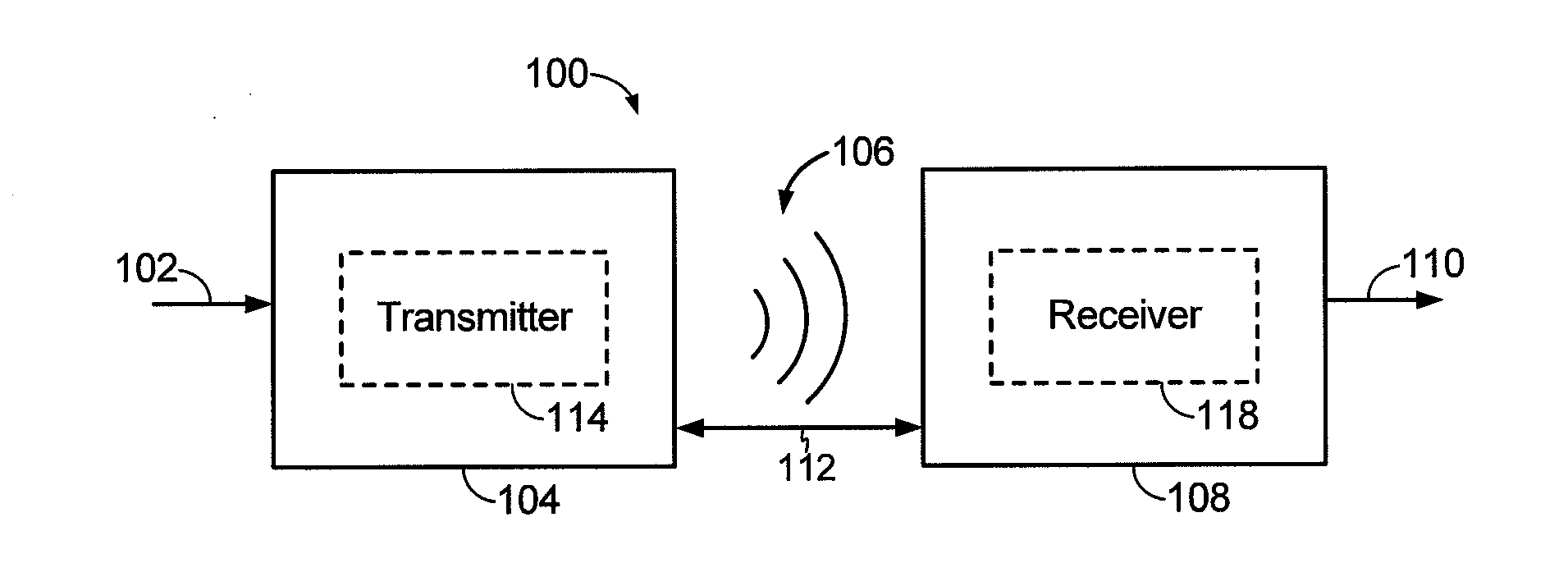
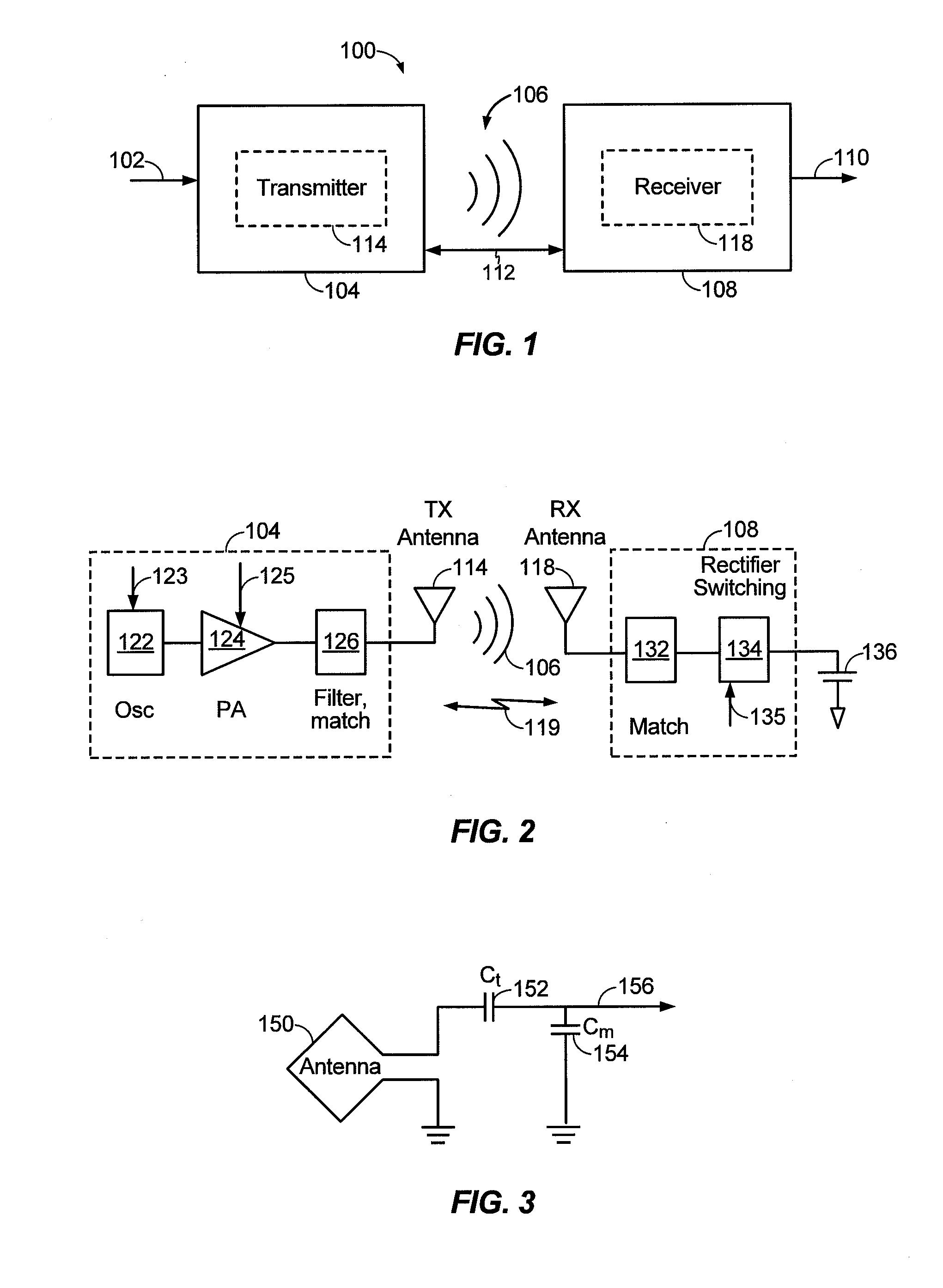
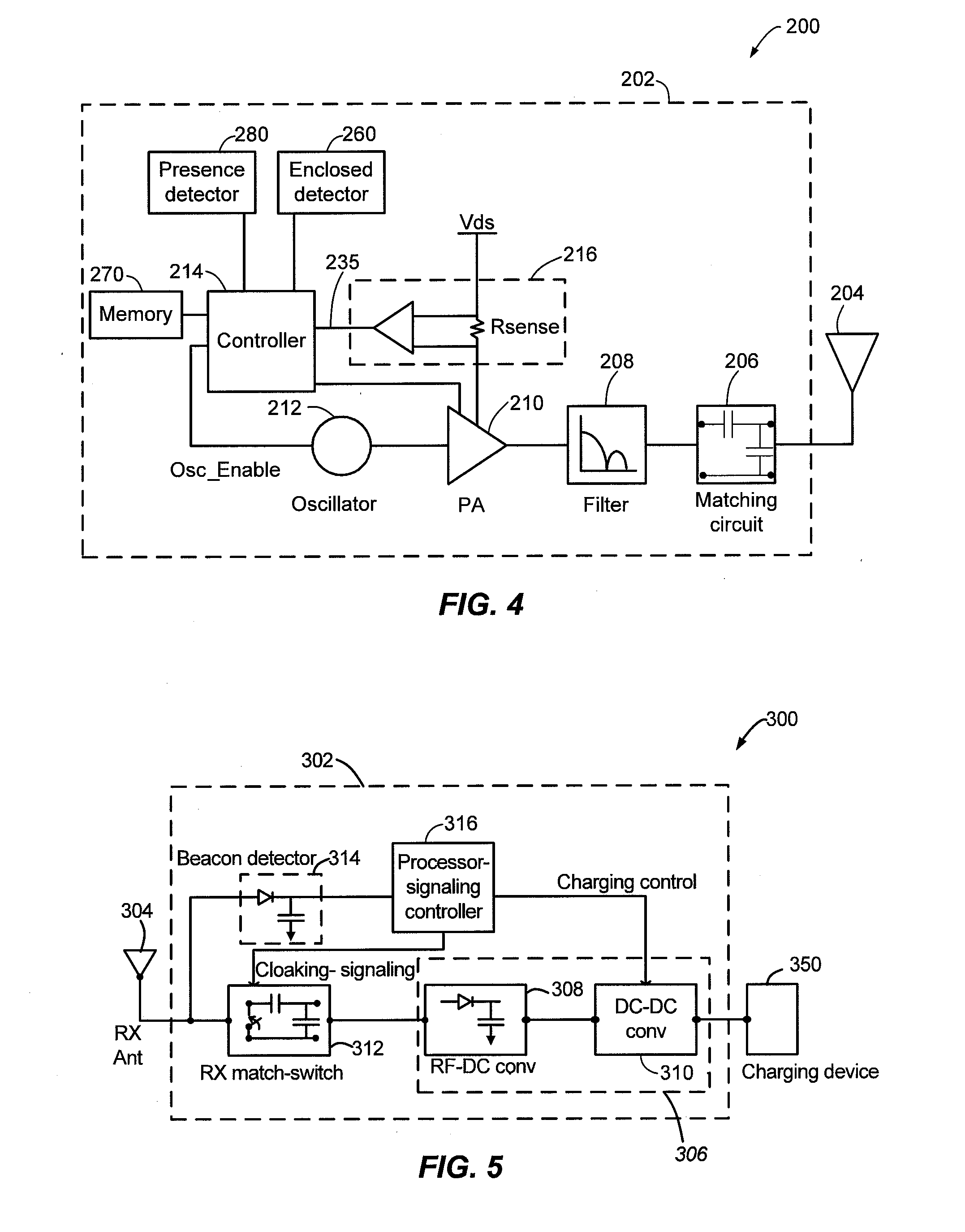
[0026]The detailed description set forth below in connection with the appended drawings is intended as a description of exemplary embodiments of the present invention and is not intended to represent the only embodiments in which the present invention can be practiced. The term “exemplary” used throughout this description means “serving as an example, instance, or illustration,” and should not necessarily be construed as preferred or advantageous over other exemplary embodiments. The detailed description includes specific details for the purpose of providing a thorough understanding of the exemplary embodiments of the invention. It will be apparent to those skilled in the art that the exemplary embodiments of the invention may be practiced without these specific details. In some instances, well-known structures and devices are shown in block diagram form in order to avoid obscuring the novelty of the exemplary embodiments presented herein.

[0027]The term “wireless power” is used here...


PUM


Abstract

Exemplary embodiments are directed to a coexistence of NFC and wireless power functionalities. A device may include an antenna configured to receive a signal. The device may further include a communication circuit configured to selectively couple to the antenna in a default mode of operation. The device may further include a wireless power circuit configured to selectively couple to the antenna in response to detecting that the signal is provided to power or charge a load.

Description

CLAIM OF PRIORITY UNDER 35 U.S.C. §119[0001]This application claims priority under 35 U.S.C. §119(e) to:[0002]U.S. Provisional Patent Application 61 / 422,628 entitled “SWITCHING BETWEEN NFC AND WIRELESS POWER” filed on Dec. 13, 2010, the disclosure of which is hereby incorporated by reference in its entirety.BACKGROUND[0003]1. Field[0004]The present invention relates generally to wireless power. More specifically, the present invention relates to methods and devices for selectively switching between a wireless power mode and a near-field communication mode.[0005]2. Background[0006]Approaches are being developed that use over the air power transmission between a transmitter and the device to be charged. These generally fall into two categories. One is based on the coupling of plane wave radiation (also called far-field radiation) between a transmit antenna and receive antenna on the device to be charged which collects the radiated power and rectifies it for charging the battery. Anten...

Claims


Application Information

Patent Timeline
IPC IPC(8): H04B5/00H04B17/00
CPCH04B5/0031H02J5/005H04B5/0037H02J7/00034H02J50/12H02J50/40H04B5/72H04B5/79H02J50/20H02J50/60
Inventor WILEY, GEORGE A.
Owner QUALCOMM INC
Features
  • Generate Ideas
  • Intellectual Property
  • Life Sciences
  • Materials
  • Tech Scout
  • Unparalleled Data Quality
  • Higher Quality Content
  • 60% Fewer Hallucinations
Learn More