Apparatus and method for controlling consumer electric power consumption

Active Publication Date: 2012-06-14
WESTERGAARD HENRIK
View PDF25 Cites 101 Cited by
  • Summary
  • Abstract
  • Description
  • Claims
  • Application Information

AI Technical Summary

Benefits of technology

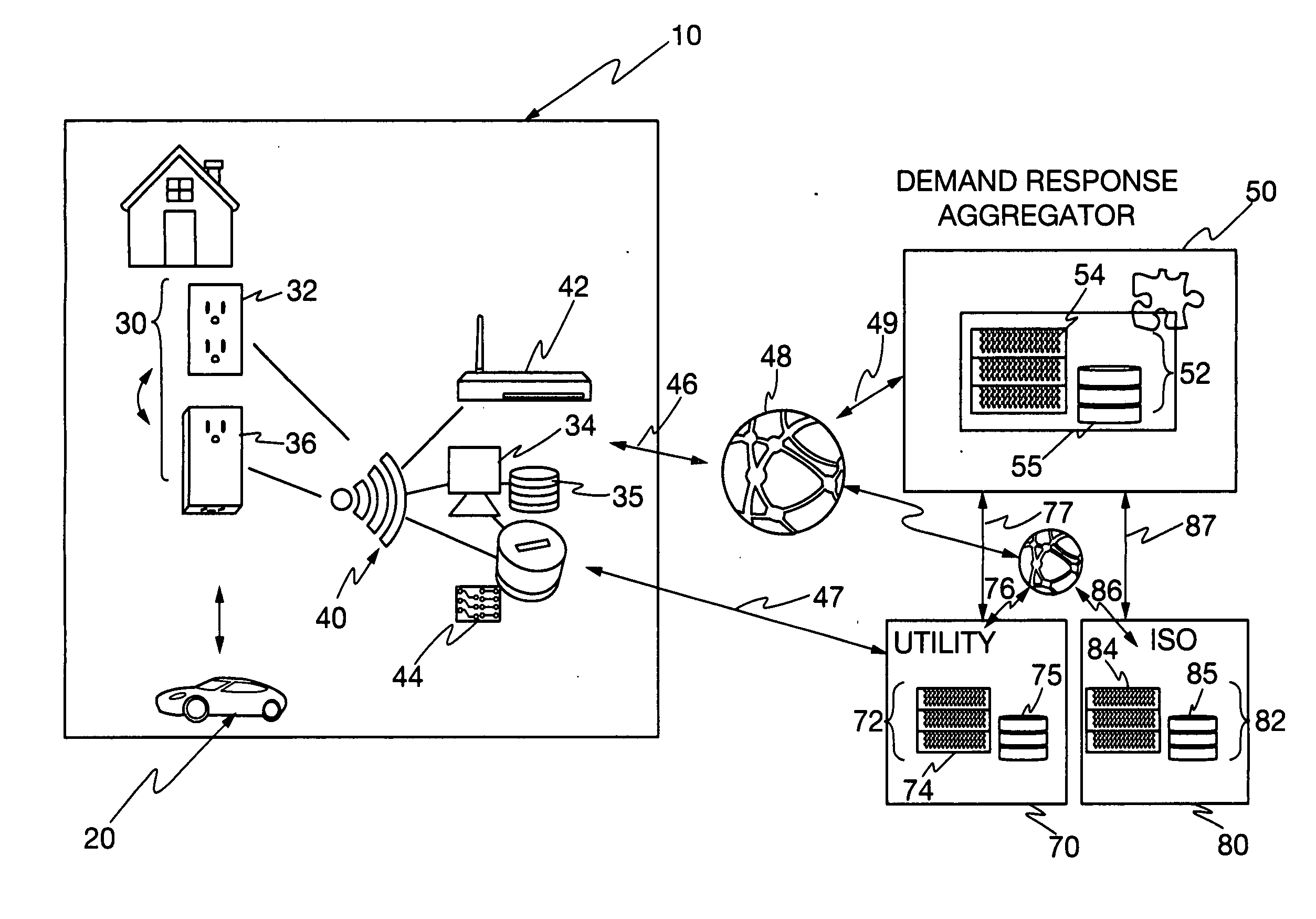
[0008]The present invention provides for a computer-implemented electric power distribution system, each of the computers within the system including a processor and associated memory from which computer instructions are executed by an associated processor, the system includes: an electric power customer having a device that consumes the electric power, the device being scheduled to start according to a policy set by the customer; an electric power provider for supplying the electric power to the device; and a load control computer system coupled to the customer and the provider, the load control computer system and having an active pool containing devices that have been started for the customer and a reservation pool for holding dev

Problems solved by technology

However, this demand is not static and may vary significantly over any given period of time.
This is wasteful of energy producing resources since excess electricity must be stored until a rise in demand is presented.
Even less desirable, the electric power company may be forced to sell the excess power supply at a loss.
In the system of Ueno et al., certain power consuming devices have high dynamic power spikes during certain phases of their operation as part of the wafer fabrication process.
The pro

Method used


Image

  • Apparatus and method for controlling consumer electric power consumption
  • Apparatus and method for controlling consumer electric power consumption
  • Apparatus and method for controlling consumer electric power consumption

Examples


Embodiment Construction

[0017]To facilitate a clear understanding of the present invention, illustrative examples are provided herein which describe certain aspects of the invention. However, it is to be appreciated that these illustrations are not meant to limit the scope of the invention, and are provided herein to illustrate certain concepts associated with the invention.

[0018]It is also to be understood that the present invention may be implemented in various forms of hardware, software, firmware, special purpose processors, or a combination thereof. Preferably, the present invention is implemented in software as a program tangibly embodied on a program storage device. The program may be uploaded to, and executed by, a machine comprising any suitable architecture. Preferably, the machine is implemented on a computer platform having hardware such as one or more central processing units (CPU), a random access memory (RAM), and input / output (I / O) interface(s). The computer platform also includes an operat...


PUM


Abstract

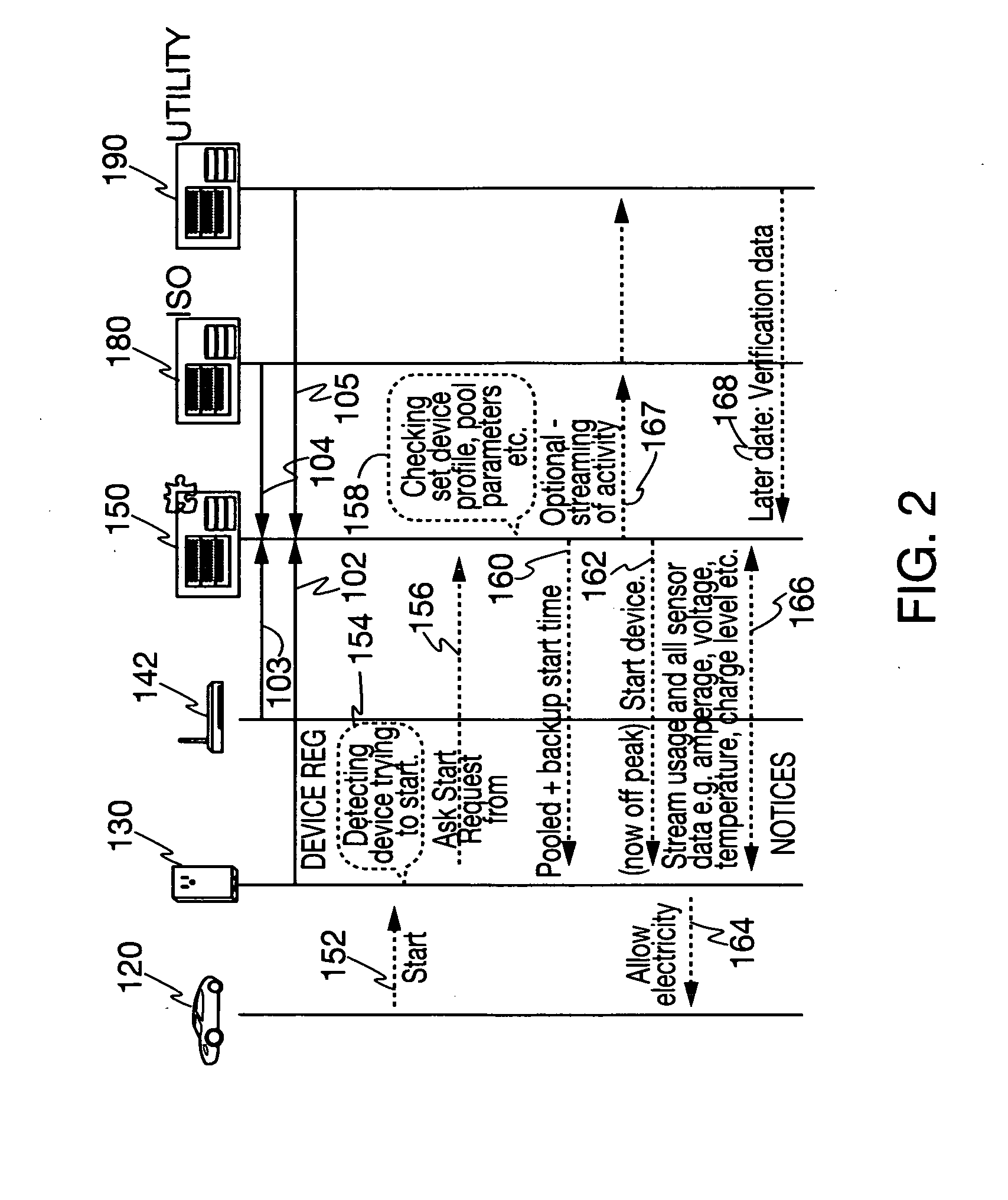
A computer-based electrical power management and allocation system is provided that collects demand for electric power usage and allocates electric power supply in satisfaction thereof. A load control server is used to collect and schedule electrical power start requests according to policies established by either or both of the electric power consumers and electric power suppliers. The energy system collects electrical power start requests and holds them in a reservation pool for later satisfaction according to prescribed customer and supplier policies and according to an overall optimization criterion of the energy system. Start messages are then subsequently issued to begin device operation once the energy system's operational criterion is relaxed and the devices are then removed from the reservation pool. Similar queuing for later satisfaction may also be applied to the distribution of other utilities, such as water, natural gas, or guaranteed interne bandwidth.

Description

CROSS REFERENCE TO RELATED APPLICATIONS[0001]This application claims priority to the U.S. Provisional Patent Application Ser. No. 61 / 459,068, titled “Apparatus and Method for Managing Consumer Electric Power Consumption,” filed on Dec. 6, 2010 and Ser. No. 61 / 519,901, titled “Apparatus and Method for Managing Consumer Electric Power Consumption,” filed on Jun. 1, 2011 the contents of each of which are herein incorporated by reference in their entirety.STATEMENT REGARDING FEDERALLY SPONSORED RESEARCH OR DEVELOPMENT[0002]Not applicable.BACKGROUND OF THE INVENTION[0003]The disclosure relates generally to an electric power management system and method of operating the same. More specifically, the disclosure relates to pooling of electric power requests according to various criteria for a subsequent, highly-ordered satisfaction of the same by the electric power utility providing the electric power to the devices.[0004]Electric service providers face an ever increasing demand for electric...

Claims


Application Information

Patent Timeline
IPC IPC(8): G05F5/00
CPCH02J3/14Y02B70/3225H02J2003/143Y04S20/222Y04S20/242Y02B70/3266Y04S50/14G05F1/66G06Q10/06313G06Q30/0202G06Q50/06H02J2310/14Y02B70/30Y04S20/00Y02B90/20G05B15/02H05K999/99
Inventor WESTERGAARD, HENRIK
Owner WESTERGAARD HENRIK
Why Eureka
Try Eureka