Turbojet including an automatically variable flow rate bleed circuit for cooling air

a technology of bleed circuit and turbine, which is applied in the field of turbines, can solve the problems of difficult to envisage, high cost of equipment, heavy equipment, etc., and achieve the effects of increasing the flow section, increasing the register speed, and speeding up the rotation speed of the magn

Active Publication Date: 2012-06-21
SN DETUDE & DE CONSTR DE MOTEURS DAVIATION S N E C M A
View PDF4 Cites 3 Cited by
  • Summary
  • Abstract
  • Description
  • Claims
  • Application Information

AI Technical Summary

Benefits of technology

[0017]For example, the shutter element may comprise a thin metal plate in which it is possible to create eddy currents. This metal plate thus expands quickly in register with the corresponding hole in the wall of the bleed chamber, thus making it possible to vary the air flow section in the desired direction. More particularly, the faster the speed of rotation of the magnet (when the speed of the turbojet increases), the greater the increase in the flow section.
[0018]In a variant, the shutter element is made of a material having a low coefficient of expansion based on a ceramic, while the wall in which said bleed hole is formed is made of a metal in which it is possible to create eddy currents. In this variant, it is thus the wall of the bleed chamber that serves to vary the flow rate by expanding.
[0019]This effect of rapidly increasing the flow section that is caused by localized heating as a result of eddy currents can be combined with any other effect due to the normal ambient heating that results merely from the fact that the temperature rises during a period of operating at full throttle (takeoff). Under such circumstances, the wall in which the bleed hole is formed and the corresponding shutter element are made of materials having significantly different coefficients of expansion, as envisaged above. The wall may be made of a magnetizable metal and the shutter element may be made of a ceramic-based composite material. The arrangement is such that the two sources of heating combine to increase the cooling air flow rate, although nevertheless with response times that are different.

Problems solved by technology

It is difficult to envisage making use of a system for adjusting the flow rate in controlled manner because that would require additional equipment to be added to the turbojet, which equipment would be expensive, bulky, and heavy.

Method used


Image

  • Turbojet including an automatically variable flow rate bleed circuit for cooling air
  • Turbojet including an automatically variable flow rate bleed circuit for cooling air
  • Turbojet including an automatically variable flow rate bleed circuit for cooling air

Examples


Embodiment Construction

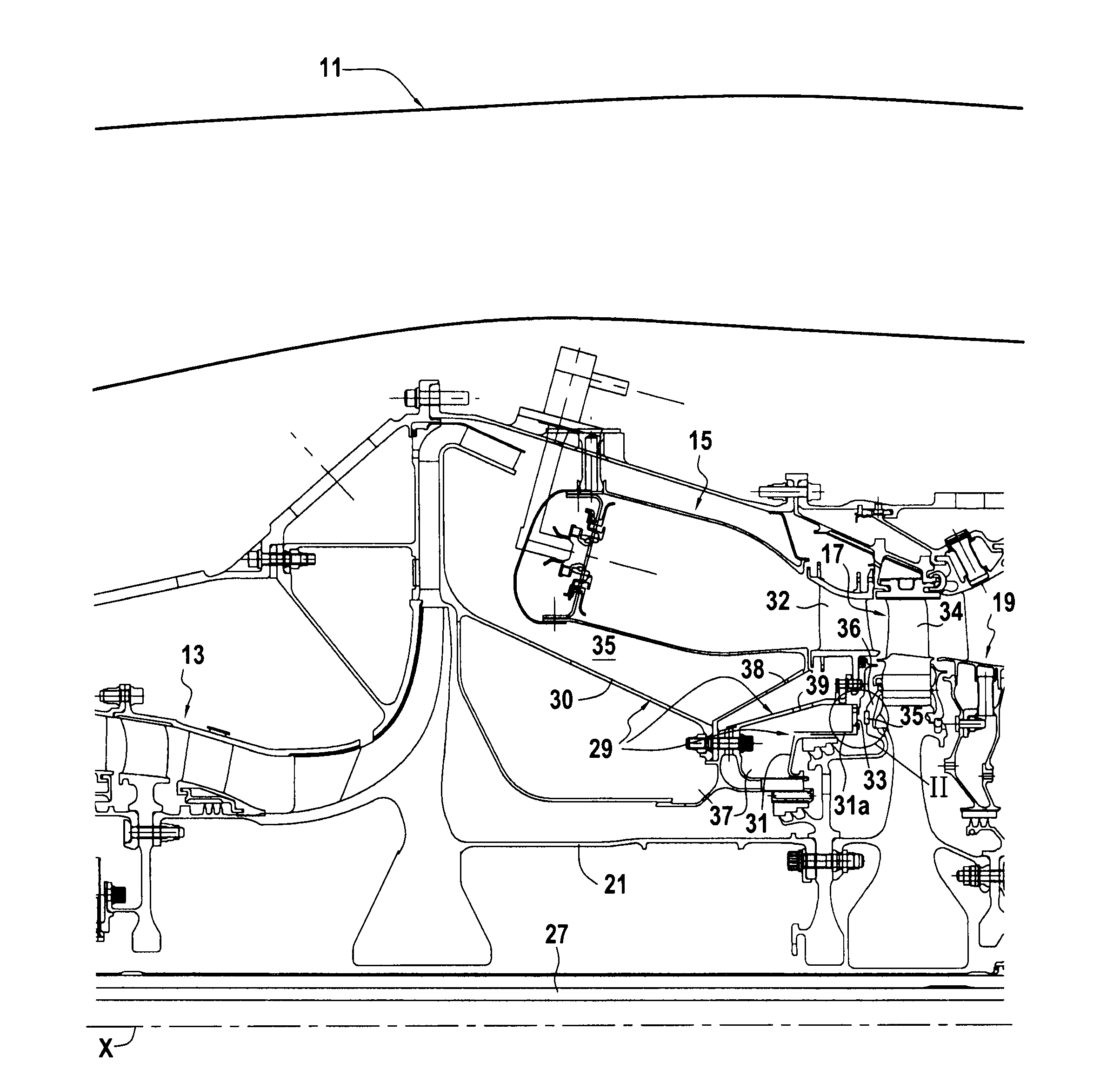
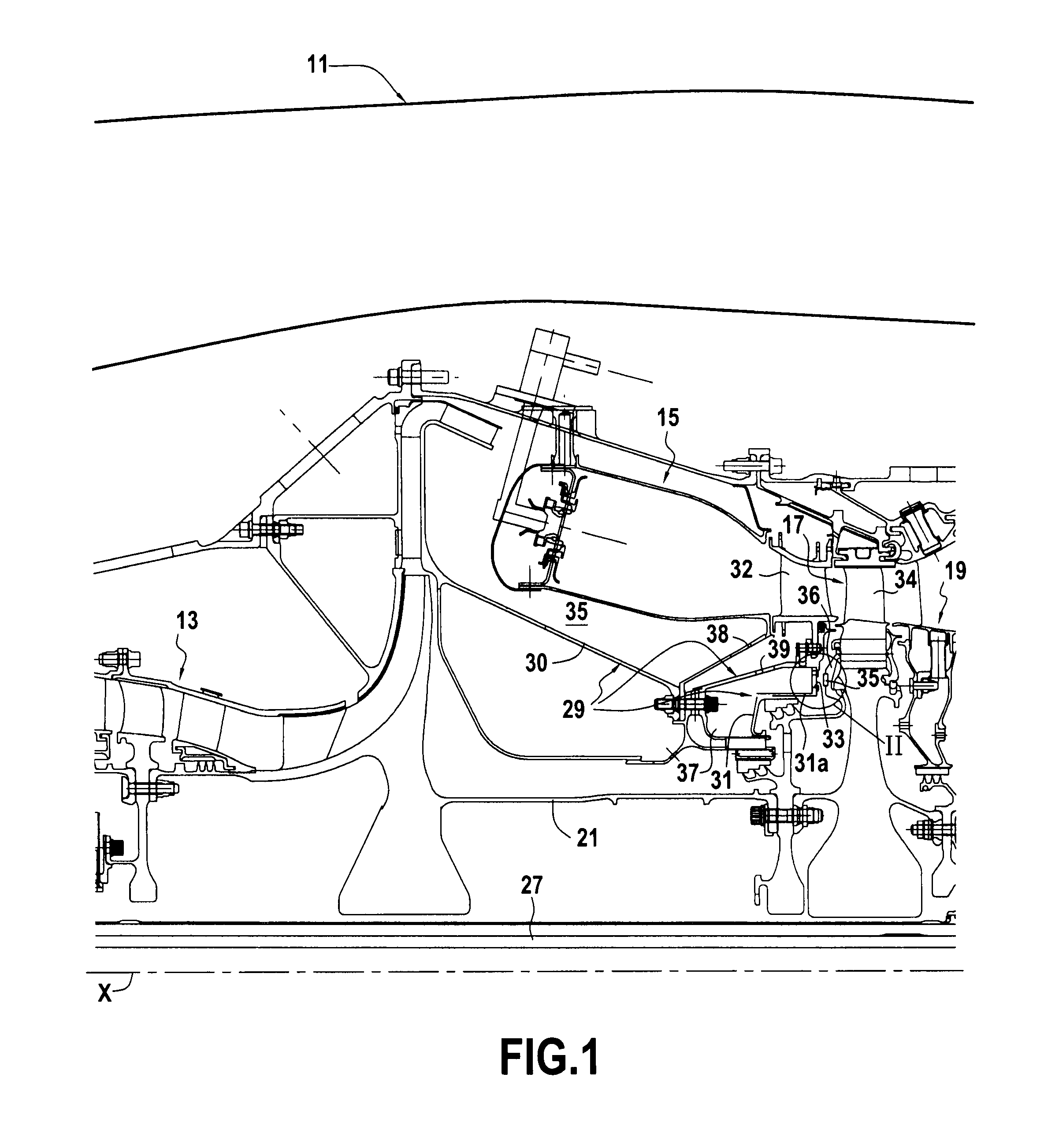
[0024]With reference to the drawings, there can be seen in part in FIG. 1, which is in axial half-section, certain portions of a turbojet 11 that are involved by the invention. There can be seen in particular the high-pressure compressor 13, the combustion chamber 15, the high-pressure turbine 17, and the low-pressure turbine 19. Conventionally, two coaxial shafts are arranged along the axis of rotation X of the rotary portions of the compressor and of the turbines. A high-pressure shaft 21 is driven by the high-pressure turbine17 and drives the rotor of the compressor 13 in rotation. A low-pressure shaft 27 is driven by the low-pressure turbine 19 and serves in particular to drive a fan (not shown) in rotation.

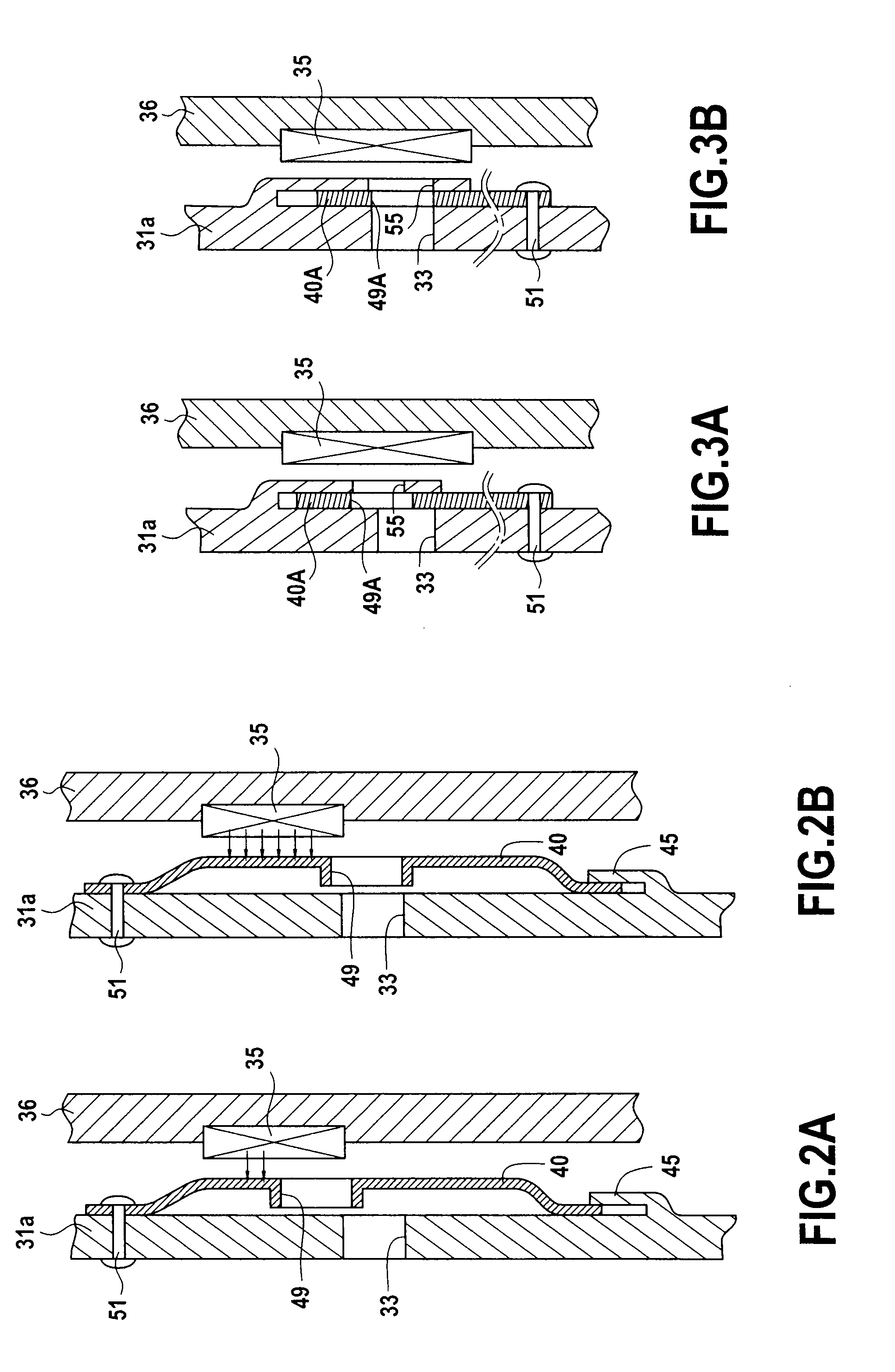
[0025]In the example, consideration is given to two particular subassemblies. A stationary, first subassembly 29 comprises the casing 30 of the combustion chamber 15, the support 31 of the nozzle 32 placed at the outlet from the combustion chamber, and the rotor 34 of the hig...


PUM


Abstract

Bleeding cooling air to cool a subassembly, e.g. such as a turbine, with automatic adjustment of the air flow section as a function of the speed of the engine. According to the invention, a shutter element is fastened to co-operate with a bleed hole, with the material that constitutes either the shutter element or the wall in which the hole is formed being of a type in which it is possible to create eddy currents, and a magnet is mounted to move past said arrangement.

Description

FIELD OF THE INVENTION[0001]The invention relates to a turbojet including at least one air bleed circuit for cooling a subassembly, such as a turbine, for example. The invention relates more particularly to an improvement that enables the cooling air flow rate to be varied as a function of the operating speed of the turbojet, by means that are simple, and that operate automatically and quickly.BACKGROUND OF THE INVENTION[0002]In an airplane turbojet, it is necessary continuously to cool certain subassemblies by a flow of relatively cool air, where such subassemblies may for example be the high-pressure turbine and / or the low-pressure turbine.[0003]By way of example, air is bled off by defining a bleed chamber in communication with a compressor, the bleed chamber having a wall that includes bleed holes to allow cooling air to escape towards the subassembly for cooling.[0004]The wall of such a bleed chamber is generally pierced by a plurality of holes that are regularly distributed ci...

Claims


Application Information

Patent Timeline
Patent Type & Authority Applications(United States)
IPC IPC(8): F02C6/06F02C6/08
CPCF01D5/081F01D25/12F02C6/08F02C7/18F05D2300/507Y02T50/672Y02T50/676F05D2270/303F05D2300/50212F02C9/18Y02T50/60
Inventor ROUSSELY-ROUSSEAU, AMAURYBERCHE, EMMANUELBURLET, GUY
Owner SN DETUDE & DE CONSTR DE MOTEURS DAVIATION S N E C M A
Why Eureka
Try Eureka