Check patentability & draft patents in minutes with Patsnap Eureka AI!

Wrap spring clutch coupling with forced spring clearance disengagement

Active Publication Date: 2012-06-21
INERTIA DYNAMICS
View PDF0 Cites 1 Cited by
  • Summary
  • Abstract
  • Description
  • Claims
  • Application Information

AI Technical Summary

Benefits of technology

[0009]A rotational coupling in accordance with the present invention represents an improvement relative to conventional rotational couplings and, in particular, conventional wrap spring clutches. By providing a mechanism that facilitates unwinding of the wrap spring independent of the relative rotation of the hubs, the inventive coupling facilitates release of the wrap spring even in applications in which the difference in rotational speed among the hubs is low. As a result, the inventive coupling can be used in additional applications previously considered unsuitable for a wrap spring clutch.

Problems solved by technology

As a result, the inventive coupling can be used in additional applications previously considered unsuitable for a wrap spring clutch.

Method used


Image

  • Wrap spring clutch coupling with forced spring clearance disengagement
  • Wrap spring clutch coupling with forced spring clearance disengagement
  • Wrap spring clutch coupling with forced spring clearance disengagement

Examples


Embodiment Construction

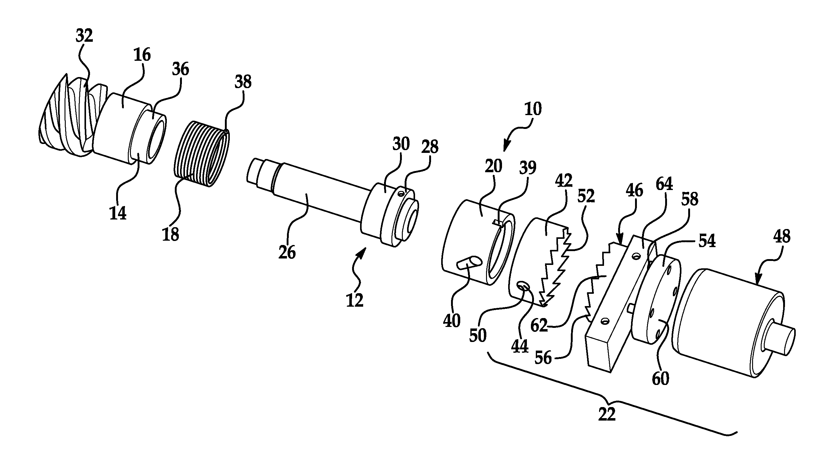
[0015]Referring now to the drawings wherein like reference numerals are used to identify identical components in the various views, FIGS. 1-4 illustrate a rotational coupling 10 in accordance with one embodiment of the present invention. Coupling 10 functions as a clutch to selectively transfer torque between input and output members such as shafts, pulleys, gears, sprocket and sheaves (not shown). Coupling 10 may also function as a brake on the output member when torque is not being transferred to the output member. In the illustrated embodiment, coupling 10 functions as a start / coast (or start / stop) clutch. It should be understood, however, that the invention could be used in other clutches such as overrunning / one-way clutches and single revolution clutches as well as clutch / brake combinations including any of the SC and WSC mechanical series clutches and / or CP and SAC actuated clutch series and / or DCB, CB and Super actuated clutch-brakes sold by Altra Industrial Motion, Inc. unde...


PUM


Abstract

A rotational coupling is provided. The coupling includes first and second hubs disposed about an axis of rotation. A wrap spring is disposed radially outwardly of the hubs and rotatably couples the hubs upon rotation of the first hub in a first rotational direction. A spring actuation member is configured for rotation about the axis and coupled to one end of the wrap spring. The opposite end of the wrap spring is coupled to the second hub. An actuator is configured to selectively stop rotation of the spring actuation member and the second hub in the first rotational direction and cause rotation of the spring actuation member in a second rotational direction to thereby unwrap the wrap spring. The rotational coupling therefore facilitates disengagement of the wrap spring from the first hub during release of the coupling to prevent undue noise and vibration and reduce wear.

Description

BACKGROUND OF THE INVENTION[0001]1. Field of the Invention[0002]This invention relates to rotational couplings and, in particular, to a wrap spring clutch having features to assist disengagement of the wrap spring upon release of the clutch.[0003]2. Discussion of Related Art[0004]A conventional wrap spring clutch includes an input hub and an output hub. A wrap spring is coupled to one of the input and output hubs by an interference fit. When rotation of the hub to which the wrap spring is connected in a first rotational direction causes the spring to tighten down upon the other hub thereby coupling the two hubs together for rotation and engaging the clutch. The spring is unwrapped, and the clutch released, when the hub to which the wrap spring is coupled stops or reverses direction or as the result of an external force that prevents rotation of the wrap spring.[0005]The operation of a wrap spring clutch depends on differences in rotational speed among the input and output hubs. In p...

Claims


Application Information

Patent Timeline
IPC IPC(8): F16D41/20F16D41/00
CPCF16D27/105F16D27/00F16D2125/582F16D2300/22
Inventor MELLOR, PATRICIA M.
Owner INERTIA DYNAMICS
Features
  • R&D
  • Intellectual Property
  • Life Sciences
  • Materials
  • Tech Scout
  • Unparalleled Data Quality
  • Higher Quality Content
  • 60% Fewer Hallucinations
Learn More