Induction cooking appliance

a technology of induction cooking and cooking coils, which is applied in the direction of induction heating, ohmic resistance heating, electric/magnetic/electromagnetic heating, etc., can solve the problems of increasing heat loss, low heat efficiency, and increasing heat generation of components such as heating coils, so as to achieve high reliability of cooling configuration and suppress the effect of temperature rise of the cooling wind

Active Publication Date: 2012-06-21
PANASONIC INTELLECTUAL PROPERTY MANAGEMENT CO LTD
View PDF4 Cites 27 Cited by
  • Summary
  • Abstract
  • Description
  • Claims
  • Application Information

AI Technical Summary

Benefits of technology

[0052]The induction cooking appliance of the present invention realizes a highly reliable cooling configuration in which the air discharged from the exhaust port and taken in again from the intake is reduced and the tempera

Problems solved by technology

Therefore, in the induction cooking appliance, the heat loss increases under a condition of relatively low heat efficiency, and the heat generation of the component such as the heating coil increases by that much.
If the temperature-raised exhaust air is again taken in,

Method used


Image

  • Induction cooking appliance
  • Induction cooking appliance
  • Induction cooking appliance

Examples


first embodiment

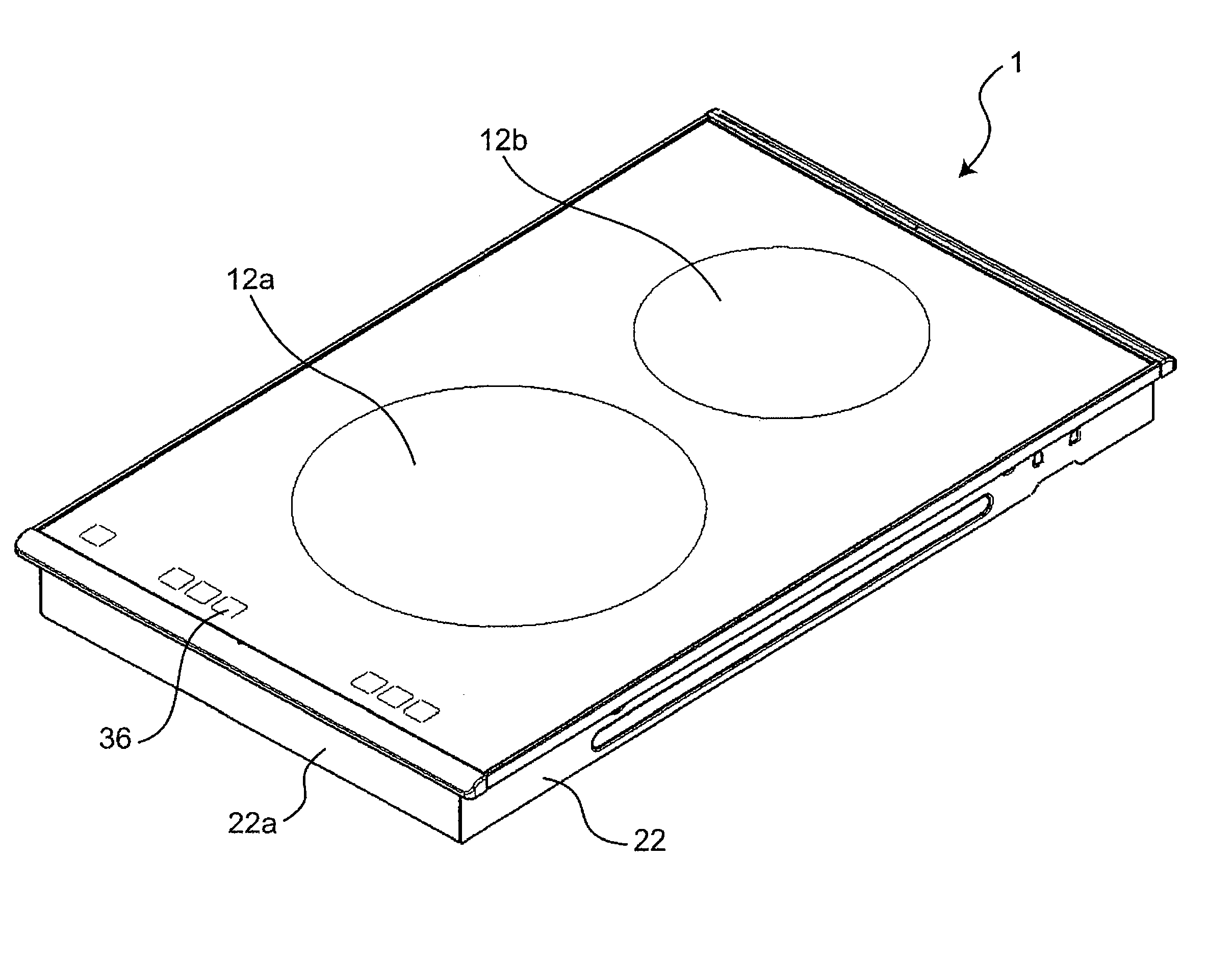
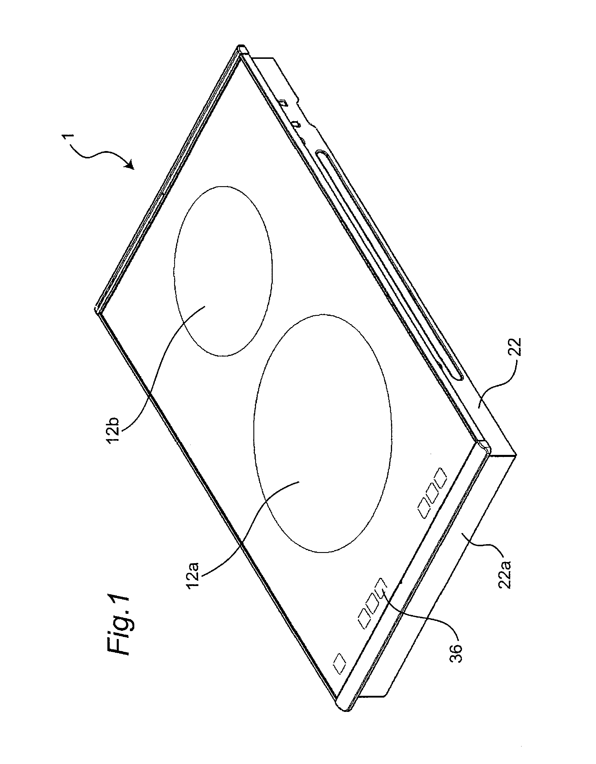
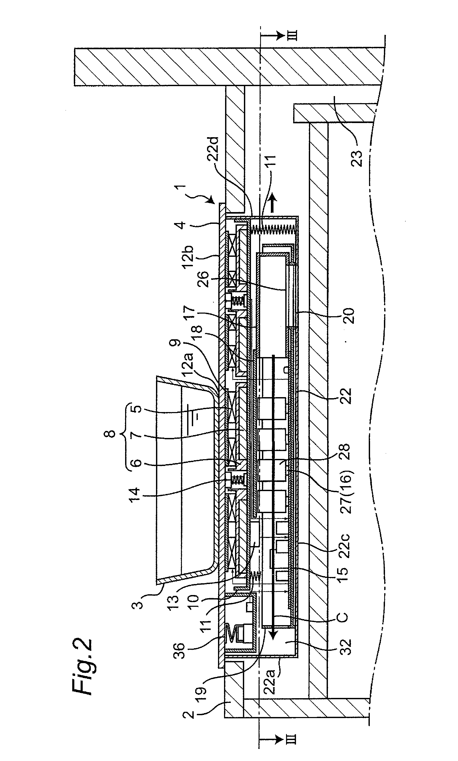
[0080]FIG. 1 is a perspective view showing an entire induction cooking appliance according to a first embodiment of the present invention. FIG. 2 is a cross-sectional view showing an installed state in which the induction cooking appliance of the first embodiment according to the present invention is incorporated in a kitchen cabinet. FIG. 3 is a horizontal cross-sectional view of the induction cooking appliance of the first embodiment according to the present invention, and is a cross-sectional view taken along line III-III of FIG. 2.

[0081]In FIG. 1, a top plate 4 for placing a cooking container 3 and the like, which is an object to be heated, is arranged on an upper surface of an induction cooking appliance 1. The top plate 4 of the first embodiment is formed with two heating regions 12a, 12b. In the induction cooking appliance 1, heating coils 5 (refer to FIG. 2) for inductively heating the cooking container 3, and the like are arranged immediately below each heating region 12a, ...

second embodiment

[0161]An induction cooking appliance according to a second embodiment of the present invention will be hereinafter described with reference to the accompanied drawings. FIG. 4 is a horizontal cross-sectional view showing an internal configuration of the induction cooking appliance according to the second embodiment of the present invention. In the induction cooking appliance of the second embodiment, the basic configuration is the same as the induction cooking appliance of the first embodiment described above, and thus the different aspect will be centrally described. In the following description of the second embodiment, the same reference numerals are denoted on the configuring elements having the same functions and configurations as the configuring elements in the induction cooking appliance 1 of the first embodiment, so that the detailed description thereof is omitted and the description of the first embodiment is applied.

[0162]As shown in FIG. 4, the induction cooking appliance...

third embodiment

[0173]An induction cooking appliance according to a third embodiment of the present invention will be hereinafter described with reference to the accompanied drawings. FIG. 5 is a horizontal cross-sectional view showing an internal configuration of the induction cooking appliance according to the third embodiment of the present invention. In the induction cooking appliance of the third embodiment, the basic configuration is the same as the induction cooking appliance of the first embodiment described above, and thus the different aspect will be centrally described. In the following description of the third embodiment, the same reference numerals are denoted on the configuring elements having the same functions and configurations as the configuring elements in the induction cooking appliance 1 of the first embodiment, so that the detailed description thereof is omitted and the description of the first embodiment is applied.

[0174]As shown in FIG. 5, in the induction cooking appliance ...


PUM


Abstract

To reduce the air exhausted to outside a main body after cooling a heat generating component from being taken in again from an intake port. The flow of cooling wind cooled the heat generating component is discharged from an exhaust port 21 at other than a first peripheral wall 19 with the flow bent inside the main body. When rectified inside the main body and discharged from the exhaust port 21, the cooling wind grows to a flow speed of a certain extent to become an exhaust air that a flowing direction is clearly defined, so that it is less likely to be taken in again from the intake port 20, it is less likely to be subjected to the influence of obstacles of the exhaust port, use can be made in a kitchen cabinet of the intake and exhaust air at the back side, and it is satisfactory and is less likely to be damaged without involving sense of unpleasantness by the exhaust air to the user.

Description

TECHNICAL FIELD[0001]The present invention relates to induction cooking appliances for inductively heating a cooking container such as a metal pan, which is an object to be heated, using a heating coil, and in particular, to a cooling structure in the induction cooking appliance.BACKGROUND ART[0002]In recent years, an induction cooking appliance is becoming commonplace in the kitchen of a general household as a safe and clean heat source that does not use fire and that does not discharge combustion gas. In the induction cooking appliance used in the kitchen, a built-in type induction cooking appliance in which a main body portion of the induction cooking appliance is fitted to an open portion formed at an upper surface of a box-shaped kitchen cabinet to arrange the main body portion of the induction cooking appliance inside the kitchen cabinet, and a cooking top plate configuring an upper surface of the induction cooking appliance is arranged so as to be exposed at the upper surface...

Claims


Application Information

Patent Timeline
IPC IPC(8): H05B6/12H05B6/42
CPCH05B2206/022H05B6/1263
Inventor MATSUI, EIJIKATAOKA, AKIRASHIGEOKA, TAKEHIKOKUSAKA, TAKAAKIOGAWA, KENJI
Owner PANASONIC INTELLECTUAL PROPERTY MANAGEMENT CO LTD
Why Eureka
Try Eureka