Illumination control system for motion and daylight in large structures

a control system and large structure technology, applied in the field of modular lighting systems, can solve the problems of increasing the overall cost of the system, increasing the cost of maintenance, and high price, and achieve the effect of cost-effective and higher-priced technology

Inactive Publication Date: 2012-06-21
KENALL MFG
View PDF4 Cites 67 Cited by
  • Summary
  • Abstract
  • Description
  • Claims
  • Application Information

AI Technical Summary

Benefits of technology

[0016]It is another object of the invention that this structure to provide improved a supplemental lighting source for commercial use which is cost effective.
[0017]It is another object of the invention that this structure to provide improved a supplemental lighting source for commercial use which requires little human interaction in the commissioning process.
[0018]It is another object of the invention that this structure to provide improved a supplemental lighting source for commercial use which comprises various zones of space operating in a synchronous fashion often associated with higher priced and more complex systems.
[0019]It is another object of the invention that this structure to provide improved a supplemental lighting source for commercial use which is retrofitable with prior systems.
[0020]It is another object of the invention that this structure to provide improved a supplemental lighting source for commercial use which integrates the functions of an occupancy sensor and a background light sensor.
[0021]It is another object of the invention that this structure to provide improved a supplemental lighting source for commercial use which provides feedback to a technician when significant LED degradation occurs.

Problems solved by technology

On the other hand, the technology can come at a price.
That price being more complex, expensive, and maintenance intensive systems.
For example, many lighting systems today require complex human interaction, or computer monitoring, during set up and commissioning, which requires a person to check out the settings and adding to the overall cost of the system.
A challenge particular to LED based luminaires is a degradation of luminosity over time.
A downside to this approach is that no feedback is given to a technician, for example, to intervene when the system needs servicing.

Method used


Image

  • Illumination control system for motion and daylight in large structures
  • Illumination control system for motion and daylight in large structures
  • Illumination control system for motion and daylight in large structures

Examples


Embodiment Construction

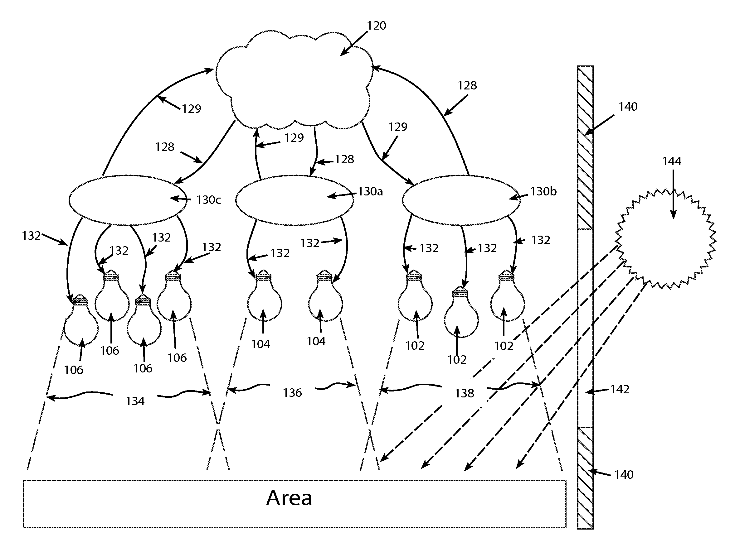
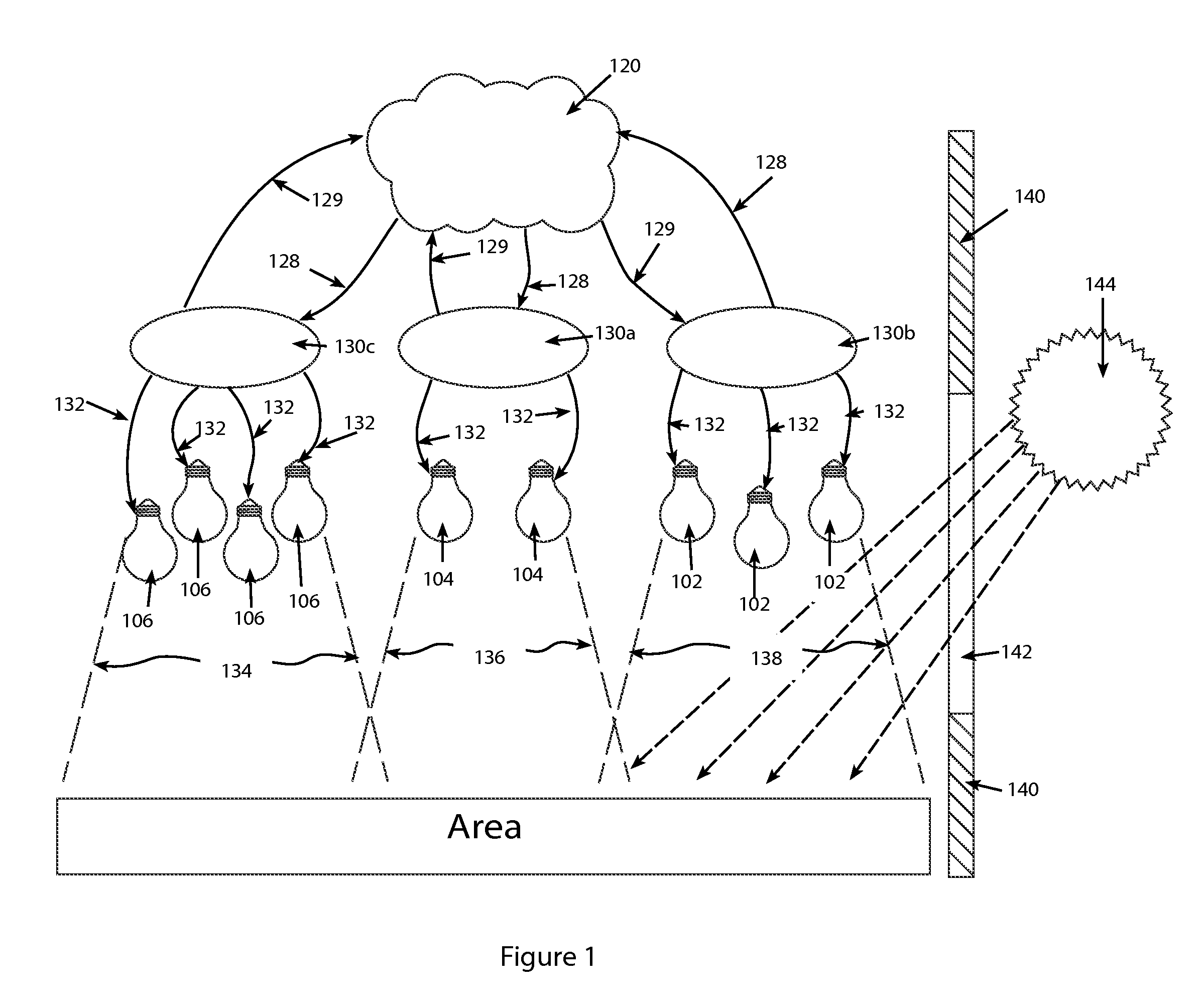
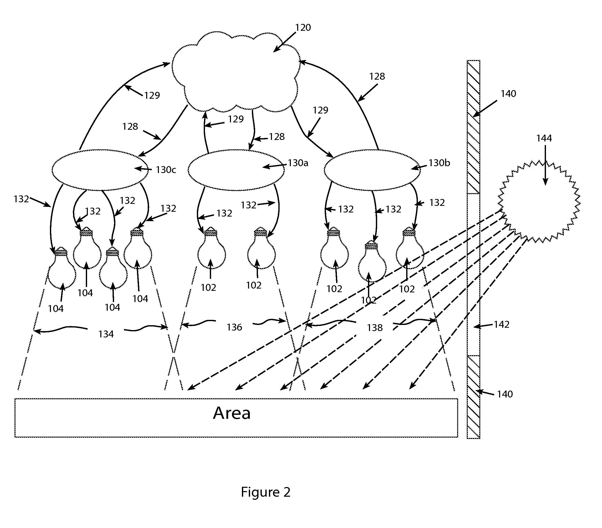
[0030]Referring to FIGS. 1-3, an area which is exposed to daylight such as the sun (144) or natural light radiation, through a window (142) or other such opening, and is also at least partially shadowed by a wall (140) ceiling or other such enclosure, can have differing light levels depending upon the position of the sun (144). Such an area can be subdivided into zones, a first zone (134), a second zone (136), up to an nth zone (138) (which can be scaled completely) each zone having differing supplemental lighting needs at different times. Supplemental lighting can be defined as the amount of artificial light to be added to a zone sufficient to meet lighting a predefined specification or requirement.

[0031]Those skilled in the art will recognize that supplemental lighting levels can be controlled in a number of ways. For example luminaire(s) (100) can be controlled by means of an analog control having different voltage levels corresponding to different levels of light output. These l...


PUM


Abstract

A cost effective illumination control system calculating motion and daylight or surrounding light inputs, particularly in large structures where the light distribution is not uniform across time. The system divides the structure into zones each having input capability with regard to occupation and background light levels. Each zone being able to make independent decisions with regard to control of lighting levels in the zone, yet the zones being able to cooperate in a coordinated fashion to provide uniform lighting to the structure as a whole.

Description

CROSS REFERENCE TO RELATED APPLICATIONS[0001]None.FIELD OF THE INVENTION[0002]The present invention relates to modular lighting systems and in particular a scalable system for controlling LED based luminaires in large structures having access to natural light with significant zones in shadow.BACKGROUND OF THE INVENTION[0003]Energy saving via controls is an area of interest in the lighting industry. More and more legislation is demanding that light fixtures be controlled when they are not in use by either lowering light levels or completely shutting off power to unneeded or redundant artificial light. In a sense this is no trivial task, as lighting, especially in public or commercial areas are quite closely tied with public and consumer utility and safety. People in modern society are becoming more accustomed to ‘smart systems’ that meet their unspoken and anticipated needs. They look for the technology to tailor to them and not the other way around.[0004]On the other hand, the techn...

Claims


Application Information

Patent Timeline
Patent Type & Authority Applications(United States)
IPC IPC(8): H05B37/02
CPCH05B37/0218Y02B20/46H05B37/0227Y02B20/40H05B47/115H05B47/175H05B47/11
Inventor DAHLEN, KEVINLEE, JIN
Owner KENALL MFG
Why Eureka
Try Eureka